Download
1 / 31
330 likes | 516 Views
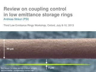
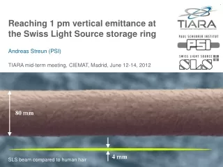
Reaching 1 pm vertical emittance at the Swiss Light Source storage ring Andreas Streun (PSI) TIARA mid-term meeting, CIEMAT, Madrid, June 12-14, 2012. 80 m m. 4 m m. SLS beam compared to human hair. Contents. TIARA work package 6 SVET The Swiss Light Source SLS Vertical emittance

E N D
Reaching 1 pm vertical emittance at the Swiss Light Source storage ringAndreas Streun (PSI)TIARA mid-term meeting, CIEMAT, Madrid, June 12-14, 2012 80 mm 4 mm SLS beam compared to human hair
Contents • TIARA work package 6 SVET • The Swiss Light Source SLS • Vertical emittance • Instrumentation • Knobs for tuning • Beam profile monitor • Methods for vertical emittance minimization • BPM roll error measurement • Magnet girder realignment • Correction of vertical dispersion and betatron coupling • Orbit manipulations and optics corrections • Random walk optimization • Vertical emittance record • Upgrade: high resolution beam profile monitor • Summary and outlook
SLS Vertical Emittance Tuning (SVET) Test Infrastructure and Accelerator Research Areawww.eu-tiara.euWork package 6 “SVET” Partially funded by the European Commission under the FP7-INFRASTRUCTURES-2010-1/INFRA-2010-2.2.11 project TIARA (CNI-PP). Grant agreement no 261905. “The main objective of SVET is to upgrade the Swiss Light Source (SLS) at PSI to enable R&D on ultra-low emittances. [...] SLS will – after this upgrade – be an R&D infrastructure suitable to investigate ultra-low vertical emittance tuning and control, in particular also in the regime of strong IBS. This is relevant for damping rings of future linear colliders and for next generation light sources.” SVET partners PSI SLS coupling suppression and controlCERNCLIC damping ring designINFN/LNF Super-B factory designMax-IV-Lab MAX-IV emittance measurement and coupling control
SVET activities • Verification of low vertical emittancebeam size (sy) & magnet optics (by) emittance ey =sy2/by High resolution beam size monitorPSI, MAX-IV-Lab • Minimization of vertical emittanceOptic correction & tuning methods and automation skew quadrupole and orbit settingsPSI, INFN/LNF • IBS simulations and measurementsIBS = intra beam scattering: increase of emittance and energy spread for high current. low energy (1.6 GeV) operation of SLS CERN, INFN/LNF, PSI
The Swiss Light Source (SLS) • Light source profile • compact lattice 288 m • medium energy 2.4 GeV • low emittance 5.5 nm • top up operation 400 ±1 mA • User operation since 2001 • 18 beam lines • 98% availability • 1 micron photon beam stability
Why the SLS storage ring is well suited for vertical emittance tuning studies • Prerequisite: high beam stability • Top up operation thermal stability • Precise beam position monitors (~100 nm[<100Hz]) • Fast orbit feedback system (0dB at 90 Hz) • Equipment for vertical emittance tuning • High resolution beam size monitor • 36 skew quadrupoles for coupling control • Dynamic alignment system (girder movers) • Experience: low coupling achieved in 2008 • vertical emittance 3.2 pm (0.06% coupling)
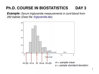
RMS beam size in SLS • Vertical beam size (sy) for ey= 1 pm • Horizontal beam size (sx) with ex= 5.5 nm • dispersion contribution (|Dx|·sp) with sp= 0.09 % 1 mm 100 mm
Vertical emittance limit Quantum emittance = vertical emittance for ideal, flat lattice • direct photon recoil,1/g radiation cone • T. O. Raubenheimer, Tolerances to limit the vertical emittance in future storage rings, SLAC-PUB-4937, Aug.1991 • independent of energy • examples: SLS 0.20 pmMAX-IV0.05 pmPETRA-III0.04 pm ultimate limit of vertical emittance quantum emittance << coupling G(s) =curvature, Cq = 0.384 pm isomagnetic lattice
vertical orbit correctors vertical orbit in quads roll errors of bending magnets • dispersive skew quads • vertical orbit in dispersive sextupoles • roll errors of dispersive quads Vertical emittance from coupling • A. W. Chao, Evaluation of beam distribution parameters in an electron storage ring, J. Appl. Phys. 50, 595 (1979) • A. Franchi et al., Vertical emittance reduction and preservation in electron storage ringsvia resonance drive terms correction, PRSTAB 14, 034002 (2011) Horizontal dipole fields Rotation (torsion) of beam(betatron coupling) Rotation of dispersion Projected e (s) Eigen-e(invariant) Vertical dispersion Apparent e (s) Monitor
Eigen-e= 9 pm Vertical emittance properties • Apparent-e oscillates around the lattice. • Oscillation amplitude is low for low coupling. • Projected-e changes at skew quad kicks. • Eigen-e is invariant. • Minimization of apparent e at one location (monitor) minimizes eigen-e too: ESRF at large coupling, figure taken from A. Franchi, Coupling correction through beam position data, LER-2011. Simulation (TRACY, 100 seeds, SLS with 6 skew quads): Eigen-e results, when optimizing on beam size at monitor () vs. optimizing on eigen-e itself ( ). • Å. Andersson et al., NIM A 592 (2008) 437
SLS knobs for coupling control • 120 sextupoles with additional coils: • 72 wired as horizontal/vertical orbit correctors. • 12 wired as auxiliary sextupoles for sextupole resonance suppression. • 36 wired as skew quadrupoles: 12 dispersive, 24 non-dispersive. • Orbit bumps in 120 sextupoles: 72 dispersive, 48 non-dispersive “skew quads”
SLS beam profile monitor The p-polarization method Å. Andersson et al., Determination of small vertical electron beam profile and emittance at the Swiss Light Source, NIM A 592 (2008) 437-446 • Image of vertically polarized visible/UV synchrotron radiation • Phase shift p between the two radiation lobes destructive interference in mid plane: Iy=0 = 0in FBSF • Finite vertical beam size: Iy=0 > 0
Measurement • Wavelength 364 nm • Get beam height from peak-to-valley intensity ratio • Lookup-table of SRW* simulations: * Synchrotron Radiation Workshop O. Chubar & P. Elleaume, Accurate andefficient computation of synchrotron radiation in the near field region, EPAC 1998.
Layout & performance • ApplicationOn-line measurementDisplay on status page X-ray side branchPinhole arrayResolution > 10mm • PrecisionBeam height 0.5 mm • ResolutionBeam height > 4 mmEmittance > 1 pm
Methods for vertical emittance minimization Overview • Measurement of BPM roll errors avoid “fake” vertical dispersion measurement. (roll error horizontal dispersion > vertical dispersion.) • Realignment of magnet girders remove main sources of vertical dispersion. (dipoles for correction of steps between girders) • Measurement and correction of vertical dispersion and betatron couplingusing skew quads. • Measurement and correction of vertical dispersion, betatron coupling & linear optics using skew quads and orbit bumps. • Random walk optimization of vertical beam size at beam profile monitor using skew quads.
BPM roll error measurements • Methods: • Local bumps (150mm) with fast orbit feedback: get BPM roll from corrector currents. • LOCO fit to response matrix. • BPM roll: 17 mrad RMS. • Origin: mainly electronics. • Corrupts measurementsof vertical dispersion. • Low level implementation as “3rd BBA* constant”: BPM sway, heave & roll ( *BBA = “beam based alignment”) M. Böge et al., The Swiss Light Source – a test-bed for damping ring optimization, Proc. IPAC-2010 Correlation of two BPM roll measurements
BAGA ( beam assisted girder alignment ) The SLS dynamicgirder alignment system • Remote positioning of the 48 girders in 5 DOF (u, v, c, h, s) by eccentric cam shaft drives. • 36 dipoles (no gradients) supported by adjacent girders. • except 3 super-bends: extra supports • except laser slicing insertion FEMTO • Magnet to girder alignment < 50 mm • girder rail 15 mm, magnet axis 30 mm S. Zelenika et al., The SLS storage ring support and alignment systems, NIM A 467 (2001) 99
Survey based girder alignment • Girder heave and pitch from survey • Align girders to medium line(long wavelengthmachine deformationis not a problem) • 400 mA stored beam currentand fast orbit feedback activeVertical corrector currents confirm girder move. M. Böge et al., SLS vertical emittance tuning, Proc. IPAC-2011
Decrease of corrector strengths through girder alignment Corrector strengths before and after girder alignment, and after beam based BPM calibration* (BBA) (sector 1)(*girder move causes vacuum chamber deformation) Corrector strengths reduced from 130to50 mradRMS.
Vertical dispersion suppression Measurement • Vertical orbit as functionof energy at 73 BPMs • Upgrade of RF oscillatorfor fast frequency shift • Prerequisite: determination of BPM roll errors. Correction • 12 dispersive skew quadrupoles ( Dx 33 cm ) • 73 12 dispersion response matrix • Suppression to <1.3 mm RMS. Vertical dispersion measurement Energy range ± 0.3%(-Df = ± 920 Hz) 20 points 10 minutes 65 mm resolution
Betatron coupling suppression Model • Sensitivity of the coupled orbit response matrix (RM)on skew quad strengths {a2}: Jacobian {RM/ a2}. • 24 non-dispersive skew quads • 73 BPMs (x/y) and 73 CH/CV 146 14624 tensor. • Rearrange: 2131624 matrix SVD-”inversion”. Measurement • Coupled orbit response matrix. (horizontal | vertical excitation vertical | horizontal orbit) Correction • Fit 24-vector {Da2} of skew quad strengths. • Apply inverse to machine: -{Da2} . • Iterate – also iterate model fit for large errors. • Compensates also betatron coupling increase from previous vertical dispersion suppression. Vertical emittance = 1.2 pm
Orbit manipulation LET algorithm (“low emittance tuning”) Principle: double linear system • Measurement vectors • vertical orbit horizontal orbit • vertical dispersion horizontal dispersion • off-diagonal (coupling)... diagonal (regular)... ...parts of the orbit response matrix • Knob vectors • vertical correctors horizontal correctors • skew quadrupoles • and BPM roll errors • Weight factors (a , w) S. Liuzzo et al., Tests for low vertical emittance at DIAMOND using LET algorithm, IPAC-2011.
LET algorithm: “all in one” • Coupling suppressionsuppression of vertical dispersion and betatron coupling • Optics correctionlike LOCO: linear optics from closed orbit • Exploits orbit bumps in sextupoles (b3) to sample off-axis quad (b2) and skew quad (a2) down-feed. • Uses dedicated skew quads for coupling suppression. • Also includes fit to BPM roll errors. Successfully applied to DIAMOND, SLS, DAFNE SLS: only 3 MD shifts emittance = 1.6 pm S. Liuzzo et al., Tests of low emittance tuning techniques at SLS and DAFNE, IPAC-2012.
Random walk optimization Model independent method • overcomes measurement limitations: BPM noise, drifts, etc. • overcomes model deficiencies. • target function: vertical beam size at profile monitor. • knobs: 24 non-dispersive skew quads. • optimization algorithm: random walk (RWO)(small steps, works even in background during user runs) RWO principle example for successful move
RWO application • Before: dispersion suppression & coupling suppression alternated and iterated emittance = 1.3 pm • Required: fine tuning of emittance monitor. • RWO ~1 hour emittance = 0.9 pm • Limitation: monitor resolution • Found reduction of coupled response matrix(although beam size was observed only in one location!) • Skew quad changes larger (6) than expectedfrom saturation of coupling suppression. systematic correction limited by model deficiencies rather than measurement errors.
Vertical emittance record • Beam size 3.6 0.6 mm • Emittance 0.9 0.4 pm • Error estimate from beam size and beta function at monitor. • Dispersion not subtracted. • SLS beam cross section (in short undulator straight, 2s) compared to a human hair: 80 mm 4 mm
Horizontal and vertical emittance of existing () and planned () storage rings low H emittance low V emittance Figure taken from R. Bartolini, Review of lattice design for low emittance ring, LER-2011 – and updated.
High resolution beam profile monitor Vertical emittance tuning limited by monitor resolution. WP6/SVET hardware investment : new monitor • Higher resolution: 2 mm[existing monitor:3.5mm] Emittance: 0.3 pm[1.0 pm] • Shorter wavelength: 266 nm[364 nm] • Larger magnification: 1.50[0.84] • Wavelength independent focusing:reflective optics: toroid[refractive optics: lens] • On-line access: extend out of tunnel[inside tunnel] • Concept:
Layout of monitor beamline X08D • Design specifications WP6 report D_SPEC due June 2012 • Installation: winter shutdown January 2013
Summary & Outlook • Methods for vertical emittance tuning established: • removing sources of vertical emittance • beam assisted girder alignment • model dependent correction • vertical dispersion and coupling suppression • LET algorithm including orbit manipulations • model independent optimization • random walk using beam size measurement • World record ey = 0.9 0.4 pm has been achieved. • 2013 program • further minimization based on new monitor • automated coupling control (feedback) • experiments on intra beam scattering using low eybeam