Download
1 / 18
180 likes | 264 Views
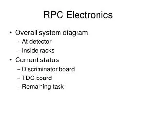
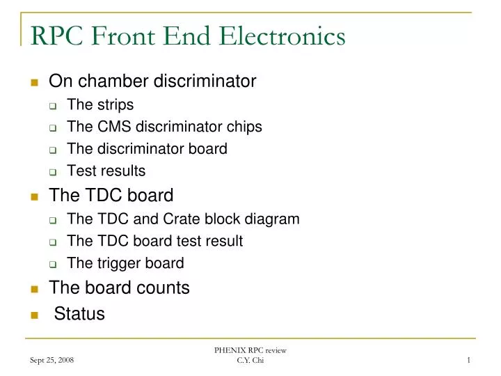
RPC Front End Electronics. On chamber discriminator The strips The CMS discriminator chips The discriminator board Test results The TDC board The TDC and Crate block diagram The TDC board test result The trigger board The board counts Status. RPC Strip.

E N D
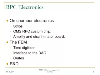
RPC Front End Electronics • On chamber discriminator • The strips • The CMS discriminator chips • The discriminator board • Test results • The TDC board • The TDC and Crate block diagram • The TDC board test result • The trigger board • The board counts • Status PHENIX RPC review C.Y. Chi
RPC Strip • Our chamber closely follows the CMS design. Our on-chamber electronics will try to follow their electronics too. • The CMS barrel strips are 1.3m long, 4 cm or 2cm wide. • 15/40 ohms impedance. 420pf/160pf capacitance. • Fully terminated strips. • CMS encap RPC • Cover 5/16 degree in phi, 7 to 38mm in width and 22 to 55 cm in length • Un-terminated. • Lemo cables are used to connect strip to the discriminator board • PHENIX RPC strip width range from 11.4 mm by 141mm to 64.6 mm by 554.2mm. • The smallest one has 46 ohms impedance and 16 pf of capacitance. • The largest one has 10 ohms impedance and 286 pf of capacitance. PHENIX RPC review C.Y. Chi
CMS RPC preamp/discriminator chip Build on AMS 0.8 um BiCMOS process, +5V device. 15 ohms input impendence. 45mW/channel. 8 channels per chip. It is designed in Bari, Italy. It has preamp, gain stage, zero crossing discriminator, monostable (cover the dead time) and LVDS driver. The chip is designed to deal with 20 fC up to 20 pC with1.7fC ENC noise. Zero crossing is necessary to deal with large dynamic range. The time walk is about .6ns except for very large charge. Testing shows that threshold level could be as high as 100fc without loosing efficiency. PHENIX RPC review C.Y. Chi
Chip production • With help of Giuseppe Isaelli and Flavio Loddo from Bari Italy, we got 4 32 channel CMS boards about 1.5 years ago. • These boards work both on the bench in Nevis and in chamber testing in University of Colorado. • We decide to use the CMS RPC chip as the frontend discriminator chips. • With help of Flavio, the chip production started at end of the last year. • The wafer is fabricated in AMS through EuroPratice and packaged in Taiwan • The chip testing is done by Matrix. (the same company did the CMS RPC chip testing) • The yield is around 99%, few bad chips out of ~2000 • We now have twice more chips than we needed in hand. PHENIX RPC review C.Y. Chi
RPC 32 channel discriminator board Cable adapter board The design is following closely the CMS design LVDS discriminator output Serial download 32 channels per board Fused +6V input analog/digital power supply ~.46A (use +5V, +3V through low drop regulators) Serial download is used to set 10 bits 4 channel threshold DAC (4mv per bin) and Fire test pulse. One DAC setting per chip. PHENIX RPC review C.Y. Chi
Connection diagram Half octant Detector Module edge 3M (Gray) 3432-5302 RPC TDC 64 ch RPC disc 32 ch 3M (Gray) 3417-6640 Adapter Board 16 short RG174 cables 2-3 m cable ? 8-18 meters cable ? 3M N3432-L302RB 3M 6834-4500PL Or 8534-4500pl 3M 4640-7300 3M (gray) 3431-5302 2-3 m cable? 8-18 meter cable ? Adapter Board 3M (Black) D89140-???? 3M (Black) 3432-5302RB Signal Cable : 40 conductors twist flat ribbon cable 3M 1700/40 Twisted Pair, Flat Cable, .050" 28 AWG Stranded Fire rating VW-1 PHENIX RPC review C.Y. Chi
On board test pulse vs. threshold study The discriminator’s threshold is moving 4mv per step. The test pulse is feed to the input amplify through 1pf cap. (not for calibration, functional check only) Channel 14 TDC distribution, DAC step =80 TDC step TDC bin size ~2.5ns Range from 0 to 43 PHENIX RPC review C.Y. Chi
Direct Pulse Injection (fixed threshold) & Cross Talk Study Channel 44 Channel 45 Channel 46 TDC No disc fired Input (steps) No disc fired disc. fired Inject test pulse through the cable adapter card + 10pf capacitance (channel 45) 2mv per step, 160mv threshold (~80fc) Cross talk seen at round 100mv on channel 46. PHENIX RPC review C.Y. Chi
DISC LVDS output at discriminator board 1.4V DISC output after ~10 meter cables 1.63V 69 ns time difference 1.61ns/ft ~42 ft Digitally subtracted pulse between + and – side of discriminator LVDS output 500mv per division Long output cable study 1 PHENIX RPC review C.Y. Chi
Long output cable study 2 The station 3 cable length could be along as 20 meters Although the result looks O.K., but this is in a lab environment. Short Cable T D C Digitally subtracted pulse Disc threshold 100 mv/div 50ns/div 79 ft cable (~24 meters) PHENIX RPC review C.Y. Chi
RPC TDC MODULE Interface Chip Collects 64 Channel Of Data L1 trigger primitives TDC serial download Trigger window L1 trigger primitives Event Data 32 channel digitizer D I S C Disc Serial download LVDS Transmitter MASK Digitized Data LVDS Receiver Serial Download Timing etc. L1 trigger etc Event Data 44X BC Test Pulse Serial download PLL Test Pulse 44X BC 4x beam clock PHENIX RPC review C.Y. Chi
TDC Module TDC: Use 44X beam crossing clock to digitized the discriminated LVDS pulse, ~2.5ns for 9.6MHz RHIC clock Test Pulse: Generated internally with the FPGA with the same 44x beam crossing clock Trigger Window: The lower and upper limits be can set channel by channel Mask: Mask bits can be set to turn off individual channel. Serial data to Discriminator Board: Control test pulse firing and discriminator threshold ( chip by chip) The TDC Internal Test Pulse Scan average TDC value Sigma on the TDC test pulse step test pulse step PHENIX RPC review C.Y. Chi
RPC FEM crate L1 primitives XMIT T D C T D C Output To L1 Clock fanout Clock Master TDCs Slow Control GTM DCM L1 optical cable RPC(HBD) crate/BUS structure 6Ux160 mm VME size PHENIX RPC review C.Y. Chi
RPC Trigger Board Transceiver blocks Arria FPGA De-serialized FEM data & format trigger data Optical transmitter 2.8 Gbits/sec Optical transmitter Trigger data from FEM 1 pair of cable per FEM RPC triggers has been layed out and proceeded to fabrication. The module can receive up to 6 (8) FEM’s trigger data The optical trigger data contains, idle, clock numbers and up to 12 16bits FEM trigger data every beam crossing. PHENIX RPC review C.Y. Chi
Channel count etc… (one side) The discriminator board is mounted on chamber The TDC, Trigger module is located in the readout crate.
Production QA • For discriminator boards • We do even/odd channel direct pulse inject through a 12 bits DAC pulser vs. threshold • We do on board test pulse test vs. threshold • For TDC boards • Fire the discriminator on board test pulse can check the data • TDC internal test pulse scan • Data to L1 trigger board test. ( still need to be works out) PHENIX RPC review C.Y. Chi
STATUS • The discriminator and TDC modules have been successfully prototyped. • Waiting for on chamber testing. • Grounding issue need to be resolved with chamber testing • CMS 32 channel board has been tested in both Colorado and BNL factory. • We are building, 40 discriminator modules, 20 TDC boards, 3 sets of crates+ clock master modules for the coming run and individual factory readout/test stand. • Trigger modules is designed and proceed to fabrication. PHENIX RPC review C.Y. Chi
Production Outlook • The production cycle normally last about 6 months. This includes, fabricating boards, buying parts, board assembly and testing. • For the RPC3 N discriminator board, we have most of parts on hand already. • We will start production around Nov this year. PHENIX RPC review C.Y. Chi