Download
1 / 21
820 likes | 3.21k Views
Fatigue Failure Due to Variable Loading. Section V. Talking Points. Variable Loading? What have we been ignoring? How rate the lifetime of fatigue or cyclic loaded parts? Endurance Limit Estimating Fatigue Life Determining the Endurance Limit Characterizing Fluctuating Stress

E N D
Fatigue Failure Due to Variable Loading Section V
Talking Points • Variable Loading? • What have we been ignoring? • How rate the lifetime of fatigue or cyclic loaded parts? • Endurance Limit • Estimating Fatigue Life • Determining the Endurance Limit • Characterizing Fluctuating Stress • Fatigue Failure Criterion Graphically
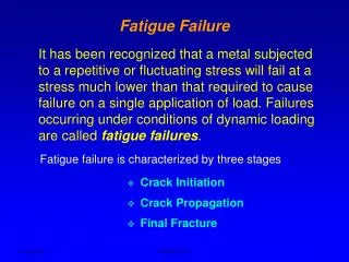
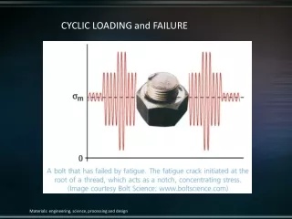
Variable Loading? • In many actual life applications, some machine members are subjected to stresses fluctuating between levels. • Often, machine members are found to fail under the action of these repeated or fluctuated stresses. • Most careful analysis reveals that the actual maximum stresses were below the ultimate strength of the material, and quite frequently even below the yield strength. • The most distinguishing characteristic of these failures is that the stresses have been repeated a very large number of times. • This type of failure is called fatigue failure.
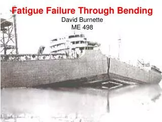
What have we been ignoring? • Suppose the countershaft is rotating • Static • Dynamic • Is fatigue an issue? • What type of stress condition do we now have if the shaft is rotating and the loads remain in a fixed direction?
D C C D Reversed Bending • As the shaft rotates the stress alternates between • Tension @ C • Compression @ D • Shaft rotates 180 degrees • Tension @ D • Compression @ C
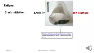
Reversed Bending - Fatigue • Common indications of reverse bending fatigue • “Beach” Marks • Dark areas indicated in this figure are representative of abrupt or “fast” fracture STRESS PATTERNS FOR REVERSE BENDING
Unidirection Bending Common Fatigue Patterns • What does each “Beach” mark represent? • Crack slowly propagated and then stops • Illustrates how the crack front propagates thru the cross-section • Failure in a threaded rod or bolt due to unidirectional bending • Rough area representing “fast” fracture
What type of loading caused this failure? Fast fracture Crack grew from the center outward UNIAXIAL TENSILE LOADING
Strain Life Ideal for low cycle fatigue applications 1≤N≤103, where N is the number of loading cycles Based on the plasticity at localized regions of the part Method is typically not practical for design use because it requires knowledge of strain concentration levels, pages 316 to 317 Fracture Mechanics Approach Requires the assumption of a pre-existing crack Used to predict growth of the crack with respect to a specified level of stress intensity Pages 319 to 323 Stress Life High fatigue life calculations 10^3≤N≤106 Large amounts of data Widely used Covered in this course How rate the lifetime of fatigue or cyclic loaded parts?
Endurance Limit • Is a stress level in a material that can withstand an infinite number of loading cycles. • In your text and throughout literature on the subject, the endurance limit is typically referenced by Se. • To determine the endurance limit we use a S-N curve • Always plotted on Log-Log Scale S - Strength of the material N - Number of cycles executed N=1 - cycle represents a load application in one direction, removal, and then once again in the opposite direction Se “Knee” of the S-N Curve
Estimating Fatigue Life • Approximating fatigue • 103≤N≤106 • Just as we saw the linear behavior of true stress-strain when plotted on log scale, the data tends to follow a piecewise linear function. • We will use this same principal to develop a power-law for estimating points in the high cycle region on the S-N diagram. Finally resulting in…
Determining the Endurance Limit • A rotary device serves as an excellent means of acquiring such data in a timely manner. • Several thousand cycles can be executed rather quickly… • Below is a sketch of a simple apparatus that can be used to determine the value of the endurance limit.
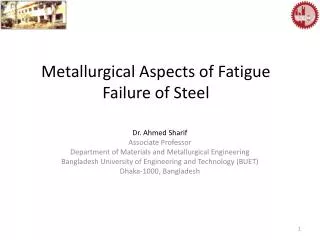
Much Endurance Data on record is for steels • Mischke, one of the authors of the text has actually done an extensive study in this area and has determined that the endurance limit of the material. • Steels • It is important to note that these estimates are for clean, highlypolished specimens that are free of surface defects. Your text emphasizes this point by the inclusion of a prime mark above the endurance limit symbol.
Endurance Limit (EL) Modifying Factors • Factors that can reduce the EL: • Surface condition, (ka) • Size factor, (kb) • Load factor, (kc) • Temperature, (kd) • Reliability factor, (ke) • Miscellaneous-effects factor, (kf) • These factors are used to adjust the endurance limit obtained from rotating beam specimens. Modified EL - Marin’s Equation Now we will discuss how to effectively estimate these modification factors.
Surface Factor, ka • Mischke performed a regression analysis to approximate the surface factor • The surface factor, ka, takes the following form: • where Sut is the minimum tensile strength and a and b are found from the table
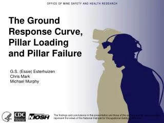
Size Factor, kb • Once again Mischke has provided a means for estimating the EL size modification factor • The size factor arises because of the geometry of the specimen used to obtain the endurance limit • Diameter 0.30 in. • Extruded or drawn bar stock • Grain elongation in the direction perpendicular to fatigue crack growth • Likelihood of surface flaws is low For larger parts are more likely to contain flaws which can result in premature material failure For axially loaded specimens the size factor is one. Effective circular cross-section may be computed for non-circular geometry (see Table 7-5.)
Loading Factor, kc • Since the usual test used to obtain the EL is the reversed bending load, modification factors are needed. • Some texts on this subject do not include this factor and require the user to implement an estimation in the EL instead.
Temperature is relatively simple to compute and understand Reliability Factor Will not be covered in detail in this course Extensive, through coverage is given to this factor in the text Statistics background is required Miscellaneous effects Corrosion Manufacturing process Residual stresses Coatings All of which can have an adverse effect on the EL Temperature, Reliability and Miscellaneous Factors
Characterizing Fluctuating Stress • Fatigue loading is oftentimes caused by a variable loading source. • To develop failure criterion for fluctuating stresses, which cause fatigue failures, we must characterize how the stress levels vary as time. • Sinusoidal stress oscillating about a static stress • Repeated Stress • Completely reversed stress
Fatigue Failure Criterion • Gerber • Modified Goodman • Soderberg