Download
1 / 25
830 likes | 3.05k Views
Electronic spectra of transition metal complexes. Characteristics of electronic spectra. Wavelength Energy of electronic transition Shape . Gaussian Band Shape - coupling of electronic and vibrational states

E N D
Characteristics of electronic spectra • WavelengthEnergy of electronic transition • Shape. Gaussian Band Shape - coupling of electronic and vibrational states • Intensity. Molar absorptivity, (M1cm1) due to probability of electronic transitions. • d) Number of bands Transitions between States of given dn configuration.
Band intensity in electronic spectra (e) Electronic transitions are controlled by quantum mechanical selection rules which determine the probability (intensity) of the transition. Transitionεmax (M1cm1) Spin and Symmetryforbidden "d-d" bands 0.02 - 1 Spinallowed and Symmetryforbidden "d-d" bands (Oh) 1 - 10 (Td) 10 – 103 Spin and Symmetryallowed LMCT and MLCT bands 103 - 5 x 10⁴
Spin Selection Rule:There must be no change in the spin multiplicity (2S + 1) during the transition. i.e. the spin of the electron must not change during the transition. Symmetry (Laporte) Selection Rule:There must be a change in parity (g ↔ u)during the transition Since s and d orbitals are g (gerade) and p orbitals are u(ungerade), only s ↔ p and p ↔ d transitions are allowed and d → d transition are formally forbidden. [i.e. onlytransitions for which Δl = ± 1 are allowed]. d → d bands are allowed to the extent that the starting or terminal level of the transition is not a pure d-orbital. (i.e. it is a molecular orbital of the complex with both metal and ligand character).
States for dn configurations • Russel-Saunders Coupling • Angular momentum of individual electrons couple to give total angular • momentum for dn configuration ML = ∑ml • Spin momentum of individual electron spins couple together to give total • spin, S = ∑s • Inter-electronic repulsions between the electrons in the d orbitals give rise to • ground state and excited states for dn configurations. • States are labeled with Tern Symbols • Electonic transitions between ground and excited states are summarized in • Orgel and Tanabe-Sugano diagrams . • Term Symbols (labels for states) contain information about L and S for state Hund’s Rules. i) Ground state has maximum spin, S ii) For states of same spin, ground state has maximum L.
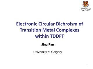
Number of d-d bands in electronic spectrum Excitation from ground state to excited stated of dn configuration Triple degeneracy of a d2 ion’s 3T2g ground state due to three possible sites for hole in t2g level Singly degenerate 3T2g ground state. Only one possible arrangement for three electrons in t2g level Triple degenerate ground state for d7 Three possible sites for hole in t2g level Singly degenerate 3T2g ground state. Only one possible arrangement for six t2g electrons.
Labeling of d-d bands in electronic spectrum. • Consider states of dn configuration • Determine free ion ground state Term Symbol (labels for states) • Assign splitting of states in ligand field • Spectroscopic labeling of bands. • Orgel diagrams (high-spin) • Tanabe-Sugano diagrams (high-spin and low-spin)
Individual electron l = 2, ml = 2, 1, 0, -1, -2 Maximum ml = l l = 0, 1, 2, 3, Orbital: s, p, d , f _______________________________ dn configuration, L = 0, 1, 2, 3, 4 Term Symbol S, P, D, F, G ML = Σ ml, maximum ML = L Spin Multiplicity = 2 S +1
Free ion ground state Term Symbols for dn configurationsTerm Symbols (labels for states) contain information about L and S for ground stateHund’s Rules. i) Ground state has maximum spin, S ii) For states of same spin, ground state has maximum L
Splitting of the weak field dn ground state terms in an octahedral ligand field Ground state determined by inspection of degeneracy of terms for given dn
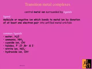
Orgel Diagrams Mn3+ Ti3+ Cr3+ V2+
Evidence for covalent bonding in metal-ligand interactionsThe Nephelauxetic Effect (“cloud expansion”) Reduction in electron-electron repulsion upon complex formation Racah Parameter, B: electron-elctronic repulsion parameter Bois the inter- electronic repulsion in the gaseous Mn+ion. B is the inter- electronic repulsion in the complexed MLxn+ion. The smaller values for B in the complex compared to free gaseous ion is taken as evidence of smaller inter-electronic repulsion in the complex due to a larger “molecular orbital” on account of overlap of ligand and metal orbital, i.e. evidence of covalency (cloud expansion”). Nephelauxetic Ratio, β = B Bo
Nephelauxetic Effect Nephelauxetic Ligand Series I < Br < CN < Cl < NCS < C2O42- < en < NH3 < H2O < F Small β Large β Covalent Ionic Nephelauxetic Metal Series Pt4+ < Co3+ < Rh3+~Ir3+ < Fe3+ < Cr3+ < Ni2+ < V4+< Pt2+~ Mn2+ Small βLarge β Large overlapSmall overlap Covalent Ionic
Cr(NH3)63+ β = 1 –hk β = 1 –(1.4)(0.21) = 0.706 Cr(CN)63- β = 1 –hk β = 1 –(2.0)(0.21) = 0.580 Bo - B = hligands x kmetal ion Bo Empirical Racah parameters, h, kβ = 1– [h(ligand) x k(metal)]
Typical Δo and λmax values for octahedral (ML6) d-block metal complexes __________________________________________________________________ Complex Δo cm-1 ~ λmax (nm) Complex Δo cm-1λmax (nm) ___________________________________________________________________________________ [Ti(H2O)6]3+ 20,300 493 [Fe(H2O)6]2+ 9,400 1064 [V(H2O)6]3+ 20,300 493 [Fe(H2O)6]3+ 13,700 730 [V(H2O)6]2+ 12,400 806 [Fe(CN)6]3- 35,000 286 [CrF6]3- 15,000 667 [Fe(CN)6]4- 33,800 296 [Co(H2O)6]3+, l.s. 20,700 483 [Fe(C2O4)3]3- 14,100 709 [Cr(H2O)6]2+ 14,100 709 [Co(CN)6]3- l.s. 34,800 287 [Cr(H2O)6]3+ 17,400 575 [Co(NH3)6]3+ l.s. 22,900 437 [Cr(NH3)6]3+ 21,600 463 [Ni(H2O)6]2+ 8,500 1176 [Cr(en)3]3+ 21,900 457 [Ni(NH3)6]2+ 10,800 926 [Cr(CN)6]3- 26,600 376 [Ni(en)3]2+ 11,500 870 ___________________________________________________________________________________
1. Assign the metal oxidation state in the following compounds. • a. K2[PtCl6] • b. Na2[Fe(CO)4] • c. [Mn(CH3)(CO)5] • 2. Account for the following: • The manganous ion, [Mn(H2O)6]2+, reacts with CN- to form [Mn(CN)6]4- which has • m = 1.95 B.M., but with I- to give [MnI4]2- which has m = 5.93 B. M. • [Co(NH3)6]Cl3 is diamagnetic, whereas Na3[CoF6] is paramagnetic ( = 5.02 B.M). • [PtBr2Cl2]2 is diamagnetic and exists in two isomeric forms, whereas [NiBr2Cl2]2 • has a magnetic moment, = 3.95 B.M., and does not exhibit isomerism. • Copper(II) complexes are typically blue with one visible absorption band in their • electronic spectra whereas copper(I) complexes are generally colorless. • Assign a spectroscopic label to the Cu2+ transition.