Download
1 / 30
300 likes | 418 Views
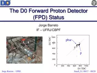
Cherenkov detector for proton Flux Measurement (CpFM ) for UA9 experiment.

E N D
Cherenkov detector for proton Flux Measurement (CpFM) for UA9 experiment 3F. Iacoangeli, 1 D. Breton, 1 V. Chaumat, 3 G. Cavoto, 1 S. Conforti Di Lorenzo, 1 L. Burmistrov, 3 M. Garattini, 1 J. Jeglot, 1 J. Maalmi, 2 S. Montesano, 1 V. Puill, 2 R.Rossi, 2 W. Scandale, 1 A. Stocchi, 1 J-F Vagnucci 1LAL, UnivParis-Sud, CNRS/IN2P3, Orsay, France 2 CERN - European Organization for Nuclear Research, CH-1211 Geneva 23, Switzerland 3 INFN - Roma La Sapienza, Italy
Outline • UA9 experiment at SPS • LUA9 project • CpFM detection chaincomponents • Opticalsimulations on the Cherenkovradiator • Beam tests at BTF of simplified prototypes (October 2013) • Beam test at BTF of the CpFM full chain (April 2014) • First preliminary results of the beam test • Conclusions
UA9 experiments • The main purpose of UA9 is to demonstrate the possibility of using a bent silica crystal as primary collimator for hadron colliders . • Bent crystal works as a “smart deflectors” on primary halo particles θch≅ αbending amorphous channeling R. W. Assmann, S. Redaelli, W. Scandale, “Optics study for a possible crystal-based collimation system for the LHC”, EPAC 06c <θ>MCS≅3.6μrad @ 7 TeV θoptimal @7TeV≅ 40 μrad UA9 experiment runs in SPS since 2009
Crystal assisted collimation • If the crystalline planes are correctly oriented, the particles are subject to a coherent interaction with crystal structure (channeling). • This effect impart large deflection which allows to localize the losses on a single absorber and reduces the probability of diffractive events and ion fragmentation
LUA9 projectUse bent crystal at LHC as a primary collimator LHC beam pipe (primary vacuum) To monitor the secondary beam a Cherenkov detector, based on quartz radiator, can be used. Aim: count the number of protons with a precision of about 5% (in case of 100 incoming protons) in the LHC environment so as to monitor the secondary channelized beam. • Main constrains for such device: • - No degassing materials (inside the primary vacuum). • - Radiation hardness of the detection chain (very hostile radioactive environment). • - Compact radiator inside the beam pipe (small place available) • Readout electronics at 300 m • Cherenkov detector for proton Flux Measurements (CpFM)
CpFM detection chain components Radiation hard quartz (Fused Silica) radiator • Flange with custom viewport to realize UHV seal and optical air/vacuum interface Movable bellow Quartz/quartz (core/cladding) radiation hard fibers. • USB-WaveCatcher read electronics. For more details see : • USING ULTRA FAST ANALOG MEMORIES FOR FAST PHOTO-DETECTOR READOUT(D. Breton et al. PhotoDet 2012, LAL Orsay) The Cherenkov light will propagate inside the radiator and will be transmitted to the PMT throughout the bundle of optical fibers. Radiator must work as waveguide. The first prototype of CpFM will be installed and tested in SPS
Geant 4 OpticalSimulation - We performed many simulation of the optical behavior of detection chain to define the best configuration Differentreflectioncoefficient Angle wrt the fiberaxis At the radiator surface At the end of detection chain The number of p.e. is strongly dependent on reflection coefficient
BTF Test Setup (October 2013) LAL Cerenkov INFN Cerenkov e- Beam BTF Remote ControlTable BTF Calorimeter
Radiatorwithfibers bundle Charge per Electron (normalized to electron path length into the radiator) 47° Opticalgreaseat interfacesbetweenfibers, PMT and radiator Radiator/beam angle The width of the peak is compatible with the angular aperture of the fibers The best geometry is with the radiator which cross the beam with 47° angle and the fibers coupled with the same angle so as to use all the angular acceptance of fibers We need the light arrive to the fibers with a angle compatible with angular acceptance
Best configurationforCpFM • Radiator cross the beam perpendicularly, due to small place available • Fibers are coupled with 43° angle, so as the incoming light is at 47° angle Beam Fibers Quartz • Flange brazed configuration or commercial viewport configuration • “I” shape or “L” shape, so as to increase the quartz crossed by beam ̴ 43˚ The “double bar” configurationwillbeusefultomeasure the diffusionof the beam and the background
New BTF Set-up ofCpFM (April 2014) 4 Cherenkov bars (L and I shape) 47º end of the bars MCP-PMT Fibers bundle PMTsblackboxes Fibers bundle
CpFM Test Setup @ BTF (April 2014) The setup was almost the same of last test beam , except for the long fibers bundle and for the readout provided by WaveCatcher board.
Tested configurations • Configuration A: Trioptics Quartz bars (L curved bars) + bundle + PMT • Configuration B: Optico AG L + I bars + bundle + PMT • Configuration C: I bar + PMT (direct coupling) • Configuration D: I bar + glass plate (thickness=3,85 mm) +PMT • Configuration E: I bar + glass plate (thickness=3,85 mm) +bundle + PMT (simulation of a viewport) • Configuration F: quartz I bar with a black tape around it + bundle + PMT (simulation of an absorber around the bar) • Configuration G: bundle in the beam For all these configurations, • The signal is recorded by the WaveCatcher 8 channels module
“L” and “I” bars + bundle + PMTs (R7378A) • “ I ” bar configuration • Higher light signal, due to a better surface polishing • Number of detected p.e. quite linear “L” yield less signal than “I” • “ L” bar configuration • Lower light signal, due to a worst surface polishing • Detected p.e. increase when beam came near to the fiber bundle • In principle more light produced in the 3 cm fused silica along the beam direction (“L” shorter arm) The polishing, difficult because of the “L” shape, must be enhanced. Reflectivity is essential feature of radiator bundle
Optical AG Fused Silica bars Well polished “I” bar: it is possible to distinguish the reflection points along the bar Worse polished “L” bar: the light appears more widespread and only few reflection points are visible
Mounting configurations • Another result was obtained by the study of mounting with viewport At the start we proposed 2 different mounting configuration • Flange brazed configuration • Better light transport (no viewport interfaces) • Better mechanical strength • Loss of light in the brazed points • Technological problems to braze Fused Silica with iron flange • Viewport configuration • Worst light transport (viewport interfaces) • More complex mechanical set-up • No technological problems The brazed flange is still under development
Effect of the viewport Configuration:“I” bar + quartz plate+ bundle + PMT • CpFM output with viewport= 1.2 p.e/ incident electron • Signal per e- ( @ 800 kV) : • without window: 10.5 mV • With window: 6.0 mV • Reduction of the signal is about 40 % Few-particles regime (<4 e-) The insertion of a quartz plate (thickness = 3.85mm) between the quartz output and the fibers bundle decreases the signal by a factor less than 2 The CpFM with viewport is a suitable solution
CpFM and BTF Calorimeter correlation Few-particles regime (<4 e-) The study of measured CpFM charge (normalized on the charge of single p.e.) as a function of BTF calorimeter charge shows a rather linear dependence.
Conclusions • We have evidence that the full chain (radiator + quartz window + fiber bundle + PMTs) works well, also for low fluxes • We need more time to finish analysis of the data. All the measurements need to be compared with simulations as well • We chose the “I” shape bars and the mounting with viewport for the first CpFM • The obtainedsignal is ~1 p.e. per incident e-. It can be improved by a factor 5 or 6 by means of very well polished L bars (not yet available). • The brazing of the quartz bars with a flange needs of a long collaboration process with a specialized company. It’s not possible for the installation of the CpFM in SPS this winter but it has to be done for the future (LHC) • We have measured 250 ps of time spread for the best timing configuration of CpFM. This features can be improved using a faster readout electronics.
Channeling effect of the charged particles in the bent crystal Mechanicallybentcrystal Usingof a secondary curvature of the crystal to guide the particles
Multi stage collimation as in LHC • The halo particles are removed by a cascade of amorphous targets: • Primary and secondary collimators intercept the diffusive primary halo. • Particles are repeatedly deflected by Multiple Coulomb Scattering also producing hadronic showers that is the secondary halo • Particles are finally stopped in the absorber • Masks protect the sensitive devices from tertiary halo 0 beam core primary halo 6 6.2 secondary halo & showers 7 secondary halo & showers 10 secondary collimator 1m CFC secondary collimator 1m CFC primary collimator 0.6 m CFC Normalizes aperture [σ] tertiary collimator absorber 1m W tertiary halo & showers >10 Sensitive devices (ARC, IR QUADS..) masks • Collimation efficiency in LHC ≅ 99.98% @ 3.5 TeV • Probably not enough in view of a luminosity upgrade • Basic limitation of the amorphous collimation system
2011 data protons 2012 data protons (270 GeV) Reduction factor (Lam / Lch) Loss rate along the SPS ring • Loss map measurement in 2011: intensity increased from 1 bunch (I = 1.15 x 10¹¹ p) to 48 bunches, clear reduction of the losses seen in Sextant 6. • Loss map measurement in 2012: maximum possible intensity: 3.3 x 10¹³protons (4 x 72 bunches with 25 ns spacing), average loss reduction in the entire ring !
CpFM detection chain components • Fused Silica HPFS 7980 • (M. Hoek, “Radiation Hardness Study on Fused Silica”. RICH 2007) • Fibers with core and cladding made of fused silica • (U. Akgun et al., "Quartz Plate Calorimeter as SLHC Upgrade to CMS Hadronic Endcap Calorimeters", CALOR 2008) • Hamamatsu R672 & R7378A • (A. Sbrizzi LUCID in ATLAS )
Time resolution - Time resolution measurements were performed with multi-particles events (Ne=236) so as to have at least 1 particles in the first microbunch. RMS=266ps Ne=236 RMS=455ps 10 ns We don’t know the cause of the 2 distinct distributions 20 ns • We measure the delay from trigger edge (LINAC NIM Timing signal) of the first particle of each event • The CpFM take out a distribution similar to the CALO’s one but by far less light
I bar with + bundle + PMT1 last run 235(lowflux) Online analysis Preliminary Preliminary We have a signal even in the single-particle regime