Download

1 / 27
300 likes | 414 Views
Learn about integrated circuits (IC), their logic gates, scale integration, technologies, digital components, and circuits such as decoders, encoders, multiplexers, shift registers, counters, and memories. Gain insights into different IC types and functionalities.

E N D
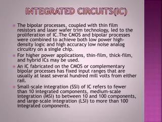
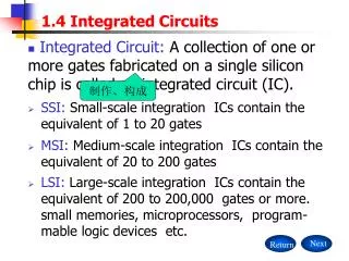
Integrated Circuit (IC) • A silicon crystal (chip) containing electronic components that create the logic gates we’ve been looking at • SSI – Small Scale Integration • MSI – Medium Scale Integration • LSI – Large Scale Integration • VLSI – Very Large Scale Integration • These refer to the number of logic gates contained on the chip
Technologies • TTL – Transistor-Transistor Logic • ECL – Emitter-Coupled Logic • MOS – Metal-Oxide Semiconductor • CMOS – Complementary Metal-Oxide Semiconductor • These refer to the underlying characteristics of the process for turning silicon into gates
Digital Components • Decoder • Encoder • Multiplexer • Register • Shift Register • Counter • Memory
B0 0 B1 1 B2 2 3 Combinational Logic 4 5 6 Enable 7 Decoder • Convert n input bits to a single output bit • For example: converting binary to octal (3-to-8) • What does the circuit look like? • Start with a truth table
Decoders can be chained Enable bit acts as the 4th input bit We now have a 4-to-16 decoder 0 B0 1 B1 2 B2 3 Combinational Logic 4 5 6 Enable 7 0 B0 1 B1 2 B2 3 Combinational Logic 4 5 6 7 Enable Decoder Chaining
0 B0 1 B1 2 B2 3 4 Combinational Logic 5 6 7 Enable Encoder • Inverse of a decoder • Convert one input bit to multiple output bits • For example: converting octal to binary (8-to-3)
I0 Output I1 Inputs I2 I3 Combinational Logic S0 Selectors S1 Multiplexer • Routes one of 2n input data lines to a single output line based on n selection lines • How many inputs total? • How big is the truth table?
Multiplexer • 6 total inputs (4 data lines, 2 selector lines) leads to 26 = 64 rows of truth table! • This is excessive and tedious • More conveniently shown thusly: • Built from an n-to-2n decoder with additional 2n input data lines
Multiplexer I0 I1 Output I2 I3 Not derived directly from the abridged truth table but from your knowledge of decoders S0 S1
Register • A multi-bit storage element made up of a group of flip-flops • Recall flip-flops store 1 bit each
CLR is a “clear” input for asynchronous initialization Data can be read out at any time Data is input with the clock signal, referred to as loading Loading can be further controlled through the use of additional combinational circuitry I0 A0 Clock I1 A1 I2 A2 I3 A3 Clear Register
Serial Input Serial Output Clock Shift Register • Like a “normal” register only bits can be shifted from one flip-flop to the next
General Purpose Shift Register • Bidirectional shifting (left and right) • Serial input/output • Parallel load • Parallel output • A multiplexer is provided to select the operation
General Purpose Shift Register • Multiplexer operation selection • Use a multiplexer to determine the shift operation
General Purpose Shift Register • What are they good for? • Integer multiplication by powers of 2 • Integer division by powers of 2 • Bit counting for parity • etc.
Counter • A register that cycles though predetermined states based on an external input • We’ve seen these already • You should already know how to design one of these • Parallel load/clear functionality is often added via combinational circuitry
Memory • A group of storage cells and associated access circuits • Bits are grouped into words • Words are the smallest addressable unit • Typically made up of 1 or more bytes (8-bits) • Each word in memory is assigned a unique address
Data In 2k word Memory n bytes/word Address Read Write Data Out Memory
Data In 16 1024 word Memory 2 bytes/word 10 Address Read Write 16 Data Out Memory • How many address lines? • How many data input lines? • How many data output lines?
Memory • K = “Kilo-bytes” = 210 bytes • M = “Mega-bytes” = 220 bytes • G = “Giga-bytes” = 230 bytes • May be specified in either bytes or words • Micro-processors will often talk of “Kilo-bits” or “Mega-bits” • Be careful
Memory Read/Write • Read • Apply binary address on the address lines • Apply a signal to the read input • Data is available on the data output lines • Write • Apply binary address on the address lines • Apply binary data to the data input lines • Apply a signal to the write input
Memory • Two types • RAM – Random Accessible Memory • Operations we just looked at • ROM – Read Only Memory • Has no input data lines • Has no write input • Has no read input (doesn’t need it – just acts when a valid address is supplied)
ROM • Significantly cheaper than RAM since it lacks versatility • How does the data get in there? • Mask programming – data is programmed in at the time of silicon fabrication • PROM – special programming devices allow the user to write data one time • EPROM – data is erased under ultra-violet light or electronically, but must be entirely erased and rewritten (can’t write single words)
To Do • Read chapter 2, if you haven’t already • Problems 2-1, 2-3, 2-6, 2-7, 2-8, 2-12, 2-13, 2-14, 2-16, 2-19, 2-20 • Assembly language • A sequence of ASCII characters are stored in memory (you choose where) • The length of the sequence is stored in register R0 • See next page for picture
To Do • Assembly language (continued) • Write an 8051 program to determine if the sequence is a palindrome • The output will be • R1 = 0 if the value is not a palindrome • R1 = 1 if the value is a palindrome • Test your code on various sequences (both even and odd lengths, palindromes and not palindromes) • Read chapter 4