Download
1 / 46
480 likes | 635 Views
INW Sensor Technology. …Continued. What we will cover. Installation Practices Security Changing Batteries Aqua4Plus Operation Calibration Overview. Installation Practices. Installation Practices. Above Ground Monument. Monument. Well cap. Service port. Steel or fiberglass monument.

E N D
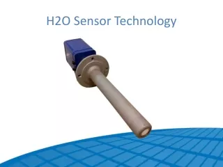
INW Sensor Technology …Continued
What we will cover • Installation Practices • Security • Changing Batteries • Aqua4Plus Operation • Calibration Overview
Installation Practices Above Ground Monument Monument Well cap Service port • Steel or fiberglass monument Strain relief Desiccant Well casing Cable Sensor
Installation Practices Monument Lid Below Ground Monument Well cap Service port • Steel or fiberglass flush mounted lid Strain relief Desiccant* Well casing * Prone to flooding!!Keep desiccant dry or use absolute sensors. Cable Sensor
Installation Practices • Do not drop into well • Lower gently to prevent damage to end of sensor.
Installation Practices • Do not scrape cable over edge of well • May nick or fray cable.
Installation Practices • Do not bend cable sharply • This may close off vent tube*. *Gauge (vented) pressure sensors contain a vent tube inside the cable. If this vent tube is closed off, readings will be wrong.
Installation Practices • Install in vertical position • Off vertical may introduce an offset.
Installation Practices • Do not lower into mud or silt • This may clog or blind sensor.
Installation Practices Use a strain relief kit to prevent excess pulling on the cable.
Installation Practices Install so that service connector stays dry.
Installation Practices On vented pressure sensors… Install so as to keep desiccant dry.
Installation Practices Replace desiccant when it turns pink. Pink = Bad Blue = Good
Security Issues Use locking monuments
Security Issues Paint to match surroundings plain painted plain painted
Security Issues Surround with a fence
Security Issues Install caution signs or alarms
Security Issues Use passworded software
Security Issues Proprietary data formats and software
Changing Batteries Should be done in a clean, dry environment to avoid contamination or moisture damage to the circuitry.
Top- cap Cable O-rings AA batteries Changing Batteries • Twisting gently, unscrew the top-cap. • Note: Two O-rings provide a water-tight seal and often seal tightly. Pulling hard can cause the O-rings to release suddenly and the top-cap to disengage with enough force to pull the insides out of the sensor.
Changing Batteries • Gently separate the top-cap from the body of the sensor. Top-cap remains attached to body via several colored wires. • Gently slide batteries out. • Insert new batteries – positive terminals towards top-cap. • Replace and retighten top-cap.
Aqua4Plus Operation Connect the sensor to your computervia Serial Port
Aqua4Plus Operation Connect the sensor to your computervia USB Port
Aqua4Plus Operation Step 1: Select a COM port Select the COM port to which your sensor is connected.
Aqua4Plus Operation Step 2: Select a sensor and take real time readings Open the sensor window by clicking on the tool button.
Aqua4Plus Operation Step 2: Select a sensor and take real time readings On the sensor map, click on the desired sensor. General information about that sensor will display to the right.
Aqua4Plus Operation Step 2: Select a sensor and take real time readings Click on the Start button to view real time readings from the sensor.
Aqua4Plus Operation Step 3: Create a recording session Open the session window by clicking on the tool button.
Aqua4Plus Operation Step 3: Create a recording session Assign a name and then describe your recording session. Click the Start button to begin the session.
Aqua4Plus Operation Step 4: Retrieve data from sensor Start the data upload by clicking on the tool button.
Aqua4Plus Operation Step 5: View the data View your data by clicking on either the table tool button or the graph tool button.
Aqua4Plus Operation Step 5: View the data Table Format Graph Format
Aqua4Plus Operation Step 6: Export data to .csv Export data to a .csv (comma separated value) file by clicking on the tool button.
Aqua4Plus Operation Step 6: Export data to .csv Export data can easily be imported into and viewed by many different analysis programs. MS Excel MS Access Modeling programs Data analysis programs
Calibration Overview
Aqua4Plus’ built in calibration calculator allows you to easily perform two-point calibrations on each channel. Calibration Overview
Calibration Overview Using the interactive calculator, enter known points and take measurements. Aqua4Plus determines the needed calibration values.
Calibration Overview Step-by-step instructions display on the calibration window for ease of reference.
What we covered Summary • Installation Practices • Security • Changing Batteries • Aqua4Plus Operation • Calibration Overview
Thank You! Instrumentation Northwest8901 122nd Ave NE, Kirkland WA, USA 98033www.inwusa.com