Download
1 / 62
620 likes | 635 Views
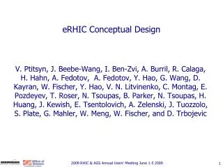
BigBOSS Pre-conceptual Design Concepts. Michael Sholl (UCB) DOE Review of BigBOSS, Dec. 6-7, 2011. Overview. The team Visible & NIR ELGs, LRGs & QSOs, the low-hanging fruit of dark energy research The survey Spectrograph trades and baseline Telescopes suitable for bigBOSS

E N D
BigBOSSPre-conceptual Design Concepts Michael Sholl (UCB) DOE Review of BigBOSS, Dec. 6-7, 2011
Overview • The team • Visible & NIR ELGs, LRGs & QSOs, the low-hanging fruit of dark energy research • The survey • Spectrograph trades and baseline • Telescopes suitable for bigBOSS • Widefield corrector • Fiber positioners • Systems engineering: throughput • Risk reduction and targeted R&D • Corrector Optics • Spectrograph • Actuators • Thermal M. Sholl, P3, 6 December 2011
Who’s working on this? • Mark Ackerman (UNM) • Eric Anderssen (LBNL) • Marco Azzaro (IAA) • Charles Baltay (Yale) • Chris Bebek (LBNL) • Santiago Becceril (IAA) • Robert Besuner (UCB) • Arjun Dey (NOAO) • Peter Doel (UCL) • Jerry Edelstein (UCB) • Will Goble (NOAO) • Bruce Grossan (UCB) • Henry Heetderks (UCB) • Patrick Jelinsky (UCB) • Dick Joyce (NOAO) • Robin Lafever (LBNL) • Michael Lampton (UCB) • Michael Levi (LBNL) • Ming Liang (NOAO) • Nick Mostek (LBNL) • Paul Perry (LBNL) • Claire Poppett (SSL) • Francisco Prada (IAA) • Eric Prieto (LAM) • Michael Raffanti (UCB) • Natalie Roe (LBNL) • David Sawyer (NOAO) • Christoph Schenk (LBNL) • David Schlegel (LBNL) • Joe Silber (LBNL) • Chao Zhai (USTC) • Zengxiang Zhou (LBNL) • …and others M. Sholl, P3, 6 December 2011
Atmospheric transmission good to 1 micron, poor beyondhttp://www.gemini.edu/sciops/ObsProcess/obsConstraints/ocTransSpectra.html J band H band K band 1.6 mm H2O at Gemini North M. Sholl, P3, 6 December 2011
Atmospheric emission manageable to about 1 micronhttp://www.gemini.edu/sciops/ObsProcess/obsConstraints/ocSkyBackground.html Sky brightness at visible wavelengths: not too horrible (linear scale) Sky brightness at NIR wavelengths: horrible (note log scale) M. Sholl, P3, 6 December 2011
Low-hanging fruit for BigBOSS • Low absorption and emission over 360-980nm band • Lyman-α from Quasi-Stellar Object (QSO) • 121.6nm rest frame (1nm=10Å) • At z ≥ 2, Ly-α redshifted to (2.2+1)×121.6nm ≥ 389nm (BigBOSS!) • [OII] doublet from emission line galaxies (ELG) • 372.7nm and 372.9nm rest frame • At z ≤ 1.6, [OII] redshifted to (1.6+1) ×372.9nm ≤ 970nm • 4000Å break of luminous red galaxy (LRG) • 4000Å rest frame • At z ≤ 1, LRG redshifted to (1+1)*400nm ≤ 800nm (BigBOSS) M. Sholl, P3, 6 December 2011
Telescope and Survey • Main goals: • 20,000,000 galaxy spectra • 14,000 square degree survey • [OII] at redshift range of z=0.5 to 1.6 • S/N=7 at a line flux of 9 × 10-17 ergs s-1 cm-2 • 1000 second exposure • Considered in exposure time calculator • Detector readnoise, dark current, quantum efficiency • Effective aperture • Reflective losses • Transmission losses (if prime focus corrector) • Spectrometer throughput • See N. Mostek talk, B4.5 • A 3.8m telescope and a 5,000 fiber multi-object spectrograph (MOS) meets these requirements M. Sholl, P3, 6 December 2011
A MOS survey is driven by greed. • How many fibers can you fit on your spectrometer(s)? • How many fiber positioners can you afford? • How many fiber positioners can you accommodate? • Our goal in defining the BigBOSS architecture is to maximize science throughput by evolutionary, not revolutionary means. • 5000 fiber positioners baselined after examining existing spectrometer and fiber positioner technology suitable for adaptation to BigBOSS. (LAMOST has 4000 positioners) • These choices lead to the following questions: • How small/large should the positioners be? • What FOV is optimal? M. Sholl, P3, 6 December 2011
Optimizing FOV & fiber patrol radius • Assume galaxy distribution in fiber patrol radius follows Poisson distribution • Vary FOV and Patrol Radius • Compute fiber efficiency and survey time nth Visit First Visit Second Visit Observe this target Success = Observe this target Success = Observe this target Success = M. Sholl, P3, 6 December 2011
5000 Fiber Optimal FOV14,000 deg2 survey, observed density of 2,300 galaxies/deg2 M. Sholl, P3, 6 December 2011
Spectrometer Considerations • 5000 fibers • Three bands (dichroic splits) • 360nm < λ < 660nm: R > 1500 • 620nm < λ < 840nm: R > 3000 • 800nm < λ < 980nm: R > 4000 • Science-specific constraints on the PSF • Maximize survey speed by matching fiber to target size • Goals of pre-conceptual design • Mass production, cost-effective high-throughput design M. Sholl, P3, 6 December 2011
Spectrometer Considerations • Benefits of pre-conceptual baseline design • Eliminate oil, grease, coupling fluids from design (air-spaced) • Use standard, robust and widely available materials • Eliminate motorized alignment motors (set once, not touched again) • Minimize optics size • Minimize obscurations • Room-temperature cameras • Off-the shelf sensors M. Sholl, P3, 6 December 2011
Spectrometer Landscape • “Before attempting to create something new, it is vital to have a good appreciation of everything that already exists in the field” • 20 existing/planned spectrometer examined • Refractive versus reflective • Collimator f/number • Camera f/number • Lens materials (by designer, evolution over time) M. Sholl, P3, 6 December 2011
Survey of Collimators used on ground-based spectrometers M. Sholl, P3, 6 December 2011
Generalizations(Exceptions likely exist) • Other than designs by Epps, collimators tend to be reflective • Faster than f/4, all existing designs are reflective • Schmidt collimators work well below f/4, but are larger than refractive collimators. • Stray light issues from light reflecting off fiber slit block • Fibers must be routed through collimator pupil (exception: VIRUS) • Pre-conceptual baseline design (Prieto talk B5.5) has f/4 refractive collimators and f/2 refractive cameras M. Sholl, P3, 6 December 2011
Pre-Conceptual Design(current baseline, September of 2011) UV NIR VIS M. Sholl, P3, 6 December 2011
Resolving power based on 50% encircled energy dλ M. Sholl, P3, 6 December 2011
Next step, investigate ~4m telescopes are compatible with BigBOSS f/4 spectrometer? • Prime focus configuration selected for BigBOSS • Rationale: • Cassegrain telescopes allow high magnification with a short package • Wide-field surveys don’t require high magnification • M2 does not magnify significantly, it acts as an aspheric plate (and a very expensive one) • A fully-baffled wide-field Cassegrain telescope requires 50% or greater central obscuration M. Sholl, P3, 6 December 2011
Design study: Can BigBOSS-like f/4.5 prime focus correctors be placed on 4m class telescopes? • Faster speed M1 = More difficult • Larger M1 = More difficult (due to C1 diameter) M. Sholl, P3, 6 December 2011
f/4.5 3º Prime Focus Correctors ~4m telescopes, increasing M1 f/# Galileo TNG M1: f/2.2 Ø3.6m DCT M1: f/1.9 Ø4.2m WIYN M1: f/1.8 Ø3.5m NTT-ESO M1: f/2.2 Ø3.5m ESO M1: f/3.0 Ø3.6m Mayall/CTIO M1: f/2.8 Ø3.8m AEOS M1: f/3.0 Ø3.7m William Herschel M1: f/2.5 Ø4.2m AAT M1: f/3.2 Ø3.9m Calar Altar M1: f/3.5 Ø3.5m CFHT M1: f/3.8 Ø3.8m M. Sholl, P3, 6 December 2011
Corrector constraints • FOV: 3° • Chief ray normal design • f/4.5 f/4 (spectrometer input) • <0.5º (mean) chief ray deviation • FRD • Jerry Edelstein to talk, 2.3, 6 December 2011 • LLF6 (used on existing Mayall corrector)is no longer available. Use fused silica, N-BK7 and LLF1 for corrector. • Maximum size of LLF1: ~0.9m diameter • Maximum corrector lens element size: 1.25m (cost-prohibitive beyond this diameter) • Focal plate may be curved, but ROC should be greater than 2.5m (as large as possible, to avoid constraints on actuators) M. Sholl, P3, 6 December 2011
Corrector Challenges • f/2.8 f/4.5 magnification • Required for fiber injection margin, and spectrometer input • Spectrometer designed for f/4 input (accommodate 500 fibers) • Magnification and chroma correction requires large, thick elements • Chromatic aberration correction necessary • 0.36 to 0.98µm PSF must enter 120µm fiber core • ADC uses LLF1 for chromatic correction and control of atmospheric dispersion • All other corrector elements can be fused silica or N-BK7 • Vignetting-free design for maximum throughput • Better performance can be achieved by allowing pupil to lie between M1 and the prime focus. This leads to 5-10% vignetting. (See Ackerman OMA designs) M. Sholl, P3, 6 December 2011
Corrector Challenges • Comparable projects and other options • LSST and DECAM are filtered imagers, and do not magnify to f/4.5 • Not suitable for MOS as currently configured (chromatic correction only over narrow filter bands) • Cassegrain and Gregorian options (use M2 for magnification) do not work well • focal plane mid-way between M1 & M2 • Geometric performance is poor • Options that use ~flat M2 for aberration correction only are unduly expensive M. Sholl, P3, 6 December 2011
Pre-conceptual Corrector Cutaway Focal Plate Fiber Actuators C3 & C4 (fused silica) ADC1 & ADC2 (LLF1, N-BK7) C1 & C2 (fused silica) Elastomeric Mounts Invar 38 Lens Cells Flexure Interfaces to Corrector Barrel Corrector Barrel (Steel) M. Sholl, P3, 6 December 2011
Atmospheric Dispersion Correction Geometric raytrace shows eects of atmospheric dispersion on telescope point spread function. a) A heavily chromatically aberrated view of the sky 60 from zenith. Overall scale is 1m square, PSF exaggerated by factor of 106. This chromatic aberration is removed by rotating the ADC prisms 85 as shown in b). The dispersion being compensated here is 3 arcsec. M. Sholl, P3, 6 December 2011
How do you correct atmospheric dispersion?Wynne (1984), Liang (2004 & 2009) Pair of doublet, zero-deviation wedge prisms LLF1High dispersion N-BK7Low Dispersion 2x ADC Drives M. Sholl, P3, 6 December 2011
Atmospheric Dispersion Compensator ADC1 Dispersion ADC2 Dispersion ADC1 Dispersion ADC2 Dispersion + = + = Atmospheric Dispersion Net ADC Dispersion Image Dispersion Image Dispersion Atmospheric Dispersion Net ADC Dispersion M. Sholl, P3, 6 December 2011
Note on ADC Near the horizon, differential dispersion across the FOV (M. Azzaro, M. Lampton) will require motion of the some fibers during an observation. This motion, called “dead reckoning” must work without the fiber view camera. M. Sholl, P3, 6 December 2011
d95 Statistics • 1530kg glass • LLF1, N-BK7, Silica • Six groups • Two aspheres • Constrained aspheric slope departure (<30µm/mm) • ADC (spherical external prism surfaces) • 15mm radial on lenses for mounts • 2.7m ROC convex focal surface, 0.95m diameter M. Sholl, P3, 6 December 2011
Pre-conceptual baseline corrector (d95) geometric blur performance M. Sholl, P3, 6 December 2011
Fiber Positioners (actuators) • 5000 fiber positioners • 3˚FOV • 12mm actuator pitch • Fiber positioning technologies • Plug Plate (a-la BOSS) • Too slow to reposition • Strongly curved focal surface (>2.5m ROC) • Echidna, tilted spine (Can work at 12mm pitch, but tilt is high) • LAMOST θ-θ (25.6mm pitch) • Reference design includes 12mm USTC actuators M. Sholl, P3, 6 December 2011
Can Echidna work for BigBOSS? • 12/sqrt(3)=6.92mm patrol radius • 160mm spine length 2.5˚ tilt relative to chief ray! Throughput loss! • System at telescope focus is f/4.5 (12.5º) • Collimator designed for f/4 input beam (14°) • System margin for fiber misalignment lies between f/4.5 and f/4. • At 1.5º field angle, an f/4.5 telescope beam requires f/3 collimator to work with Echidna! • Tilt of Echidna spines (2.5˚) leads to focal ratio degradation (FRD) and reduces system throughput significantly AND throughput is a function of fiber position within patrol disk! • Actuator tilt throughput loss can be minimized through use of a low-tip actuator topology (θ-θ or R-θ) • Requires multiple iterations, which are not suitable for “dead reckoning” M. Sholl, P3, 6 December 2011
Cobra Actuators • Cobra (θ-θ) • Innovative design • Cobra has a pitch of 8mm • Could be increased to 12mm? • Have not been deployed on a spherical focal surface • Uses Squiggle Motors, somewhat complex electronics • Reliability for 5000 actuator deployment not established • Need 6-8 iterations with fiber view camera • Not useful for dead reckoning • Expensive unit cost (Newscale) • Prototypes: $50k for five prototypes • Will investigate during R&D period M. Sholl, P3, 6 December 2011
Low-tilt actuators LAMOST 25.6mm pitch, theta-theta (USTC) SIDE 30mm pitch, theta-theta (IAA) LBNL: 20mm pitch, r-theta Efforts underway to miniaturize actuators for 12mm pitch USTC, IAA and LBNL all have promising 12mm pitch designs, with the low-tip inherent to theta-theta actuators (<0.5 degrees tip) Please see C. Zhai talk 5.4, 7 December 2011 M. Sholl, P3, 6 December 2011
BigBOSS Systems Engineering • Main task of BigBOSS Systems Engineering is management of a throughput budget • Atmospherics • Obscurations • M1 reflectivity • Corrector throughput • Material absorption • Coating reflection • Fiber injection efficiency • Chief ray normal orientation at fiber • Galaxy image size at fiber • Errors in lateral position of fibers • Fiber throughput • Spectrometer M. Sholl, P3, 6 December 2011
Optical System Throughput * * * WFC=Wide Field Corrector M. Sholl, P3, 6 December 2011
Fiber Injection Efficiency M. Sholl, P3, 6 December 2011 • Fiber injection efficiency • Galaxy image size relative to fiber diameter • Galaxy size (Sersic inverse exponential galaxy, 0.3 arcsec EE50 radius) • Atmospheric seeing (Moffat 1 arcsec FWHM, β=3.5) • Geometric blur (residual phase, as-built, thermal & dynamic) • Angular Misalignment of chief ray with respect to fiber normal • Angular Misalignment of chief ray with respect to fiber normal • Lateral misalignment of galaxy image relative to fiber • Galaxy image convolved with circular fiber to estimate throughput • Sources of misalignment between fiber and galaxy image are key to throughput budget • Astrometry errors • Focal plane thermal shifts • Dynamics (rotational mode of corrector on spider support vanes) • Fiber positioning errors (mechanical and fiber view camera) • Throughputs may be estimated by RSSing uncorrelated misalignment components or multiplying resulting throughputs
Fiber Misalignment Throughput 0.30 arcsec, EE50 radius Sersic galaxy 1 arcsec FWHM seeing Moffat Beta parameter of 3.5 M. Sholl, P3, 6 December 2011
Lateral Galaxy Position Error Breakdown • Largest uncertainties are astrometry • Currently 200mas • Tracking/pointing errors currently at 100mas • BigBOSS focal plane trackers should improve • Fiber mechanical lateral error: 125mas • Fiber defocus error: ±60µm M. Sholl, P3, 6 December 2011
Lateral Galaxy Position Error Breakdown • Largest uncertainties are astrometry • Currently 200mas • Will improve over time • Tracking/pointing errors currently at 100mas • BigBOSS focal plane trackers should improve • Fiber mechanical lateral error: 125mas • Fiber defocus error: ±60µm • Small numbers individually, but costly to throughput when included in an overall system budget M. Sholl, P3, 6 December 2011
Pre-conceptual Baseline, Risks & R&D Plan Mayall 4m telescope d95 widefield corrector with ADC September 2011 LAM f/4-f/2, 500 fiber transmissive spectrometer USTC 12mm pitch θ-θ actuators Convex IAA focal plate M. Sholl, P3, 6 December 2011
Pre-conceptual baseline risks • Mayall 4m telescope • Risks • Will Kitt Peak be shut down? • Is 4m telescope and mount compatible with BigBOSS • Strength and deflection • Cooling services • Structural dynamics • Mitigation • Ongoing investigation as to suitability of other 4m telescopes • CFHT • Blanco 4m • Blanco 4m with heavily modified DES corrector • Semi-weekly coordination meetings with Kitt Peak • FEM of existing telescope and BigBOSS implementation • Accelerometer measurement of 4m dynamics underway (accelerometers installed on Mayall prime focus cage and gathering data as we speak) • Investigation of routing paths for BB services underway M. Sholl, P3, 6 December 2011
Pre-conceptual baseline risks • d95 widefield corrector with ADC • Risks • Large corrector • Glass availability? • Corrector magnification • Glass procurement • Mitigation • Ongoing pre-conceptual structural modeling, tolerancing, mount design, exploration of alternate configurations • Glasses selected from current production capability of Schott and Corning • Examination of alternate optical configurations ongoing and TBD during R&D phase over next two years • Re-evaluation of possibility of faster, perhaps Schmidt-collimator-based spectrometer during R&D phase M. Sholl, P3, 6 December 2011
Corrector Optics R&D • Work with LBNL, Kitt Peak (M. Liang) and independent contractor (M. Ackerman) to develop and simplify corrector • Example: M. Ackerman One Mirror Anastigmat concepts M. Sholl, P3, 6 December 2011
One Mirror Anastigmat, five group, f/4.3 • 1260kg glass M. Sholl, P3, 6 December 2011
One mirror anastigmat, five-group f/3.53(requires 8mm actuator) • 1127kg glass M. Sholl, P3, 6 December 2011
What about DES corrector? • Current design works over 2.2º FOV • Vignettes significantly for larger fields (even 2.5º, see next slides) • Can DES corrector be modified to work with ADC? • Yes, with minor changes, to 2.2º FOV • Yes, with major structural modifications, to 2.5º FOV M. Sholl, P3, 6 December 2011
DECAM Baseline Corrector, 2.2˚ FOV Starting Point: 2602-v203-070122-distrib M. Sholl, P3, 6 December 2011
Vignetting of DECAM at 2.5˚ Starting Point: 2602-v203-070122-distrib M. Sholl, P3, 6 December 2011
Unacceptable vignetting of DES Corrector over 2.5° FOV M. Sholl, P3, 6 December 2011