Download
1 / 38

E N D
eRHIC Conceptual Design V. Ptitsyn, J. Beebe-Wang, I. Ben-Zvi, A. Burril, R. Calaga, H. Hahn, A. Fedotov, A. Fedotov, Y. Hao, G. Wang, D. Kayran, W. Fischer, Y. Hao, V. N. Litvinenko, C. Montag, E. Pozdeyev, T. Roser, N. Tsoupas, B. Parker, N. Tsoupas, H. Huang, J. Kewish, E. Tsentolovich, A. Zelenski, J. Tuozzolo, S. Plate, G. Mahler, W. Meng, W. Fischer, and D. Trbojevic 1
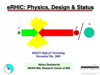
RHIC Electron accelerator 70% beam polarization goal Polarized protons 50-250 Gev (25 GeV) p e- Polarized leptons 3-10 Gev (20GeV) Heavy ions (Au) 50-100 Gev/u e+ eRHIC Scope Polarized light ions (3He) 167 Gev/u Exploration of QCD in great details: Different Center-of-Mass Energy -> Different kinematic regions Higher Luminosity-> Precision data Polarized beams -> Spin structure of nucleons (still a puzzle!) Ions up to large A -> Color Glass Condensate (state of extreme gluon densities) 2009 RHIC & AGS Annual Users' Meeting June 1-5 2009 2
ERL-based eRHIC Design • 10 GeV electron design energy. Possible upgrade to 20 GeV by doubling main linac length. • 5 recirculation passes ( 4 of them in the RHIC tunnel) • Multiple electron-hadron interaction points (IPs) and detectors; • Full polarization transparency at all energies for the electron beam; • Ability to take full advantage of transverse cooling of the hadron beams; • Possible options to include polarized positrons: compact storage ring; compton backscattered; undulator-based. Though at lower luminosity. e-ion detector Possible locations for additional e-ion detectors eRHIC PHENIX Main ERL (1.9 GeV) STAR Beam dump Low energy recirculation pass Four recirculation passes Electron source 3
ERL-based eRHIC Parameters: e-p mode 2009 RHIC & AGS Annual Users' Meeting June 1-5 2009 4
ERL-based eRHIC Parameters: e-Au mode 2009 RHIC & AGS Annual Users' Meeting June 1-5 2009 5
Electron beam R&D for ERL-based design: High intensity polarized electron source Development of large cathode guns with existing current densities ~ 50 mA/cm2 with good cathode lifetime. Energy recovery technology for high power beams Multi-cavity cry module development; high power beam ERL, BNL ERL test facility; loss protection; instabilities. Development of compact recirculation loop magnets Design, build and test a prototype of a small gap magnet and its vacuum chamber. Beam-beam effects: e-beam disruption Main R&D items for ion beam: Beam-beam effects: electron pinch effect; the kink instability … Polarized 3He acceleration 166 bunches General EIC R&D item: Proof of principle of the coherent electron cooling Main R&D Items 2009 RHIC & AGS Annual Users' Meeting June 1-5 2009 6
Polarized source development • Laser beam forms: • small central spot • ring-like (+anode bias) • ring-like • large central spot • eRHIC: ~ 250 mA average I, 20 nC/bunch • MEeICat RHIC: 50 mAaverage I, 5 nC/bunch • R&D development for a source with large cathode area and, probably, ring like cathode shape is underway (MIT-Bates, E. Tsentalovich) • Major issues: • Cathode deterioration by ion back bombardment • Cathode heating -> requires cooling Cathode deterioration measured with various shape of laser spot on the cathode confirms possible advantages of ring-like cathode shape. (E. Tsentalovich)
ERL Test Facility from D. Kayran • test of high current (several hundred mAmps) high brightness ERL operation • test of high current beam stability issues • 5-cell cavity SRF ERL • highly flexible lattice • 704 MHz SRF gun test • Start of the commissioning in 2009. Return loop e- 15-20 MeV Laser Merger system Cryo-module e- 2.5MeV SC RF Gun e- 2.5 MeV Beam dump SRF cavity 1 MW 703.75 MHz Klystron 50 kW 703.75 MHz system 5 cell SRF cavity arrived in BNL in March 2008 . 2009 RHIC & AGS Annual Users' Meeting June 1-5 2009
ERL Test Facility 2009 RHIC & AGS Annual Users' Meeting June 1-5 2009
Electron beam R&D for ERL: Linac design for eRHIC as well as for the MeRHIC 2009 RHIC & AGS Annual Users' Meeting June 1-5 2009
Recirculation Pass Optics Modification Other features: -phase trombone (in the straight sections) -path length control (at 12 o’clock region) -initial design for separator/merger The optics based on Flexible Momentum Compaction cell provides achromatic and isochronal transfer through each arc and allows for flexible adjustment of R56 parameter.
Four recirculation passes: • Separate recirculation loops • Small aperture magnets • Low current, low power consumption • Minimized cost 5 mm 5 mm 5 mm 5 mm eRHIC 10 GeV (20 GeV) 8.1 GeV (16.1 GeV) Common vacuum chamber 6.2 GeV (12.2 GeV) 4.3 GeV (8.3 GeV) Prototypemagnets are already built (V. N. Litvinenko) 2009 RHIC & AGS Annual Users' Meeting June 1-5 2009
Beam-beam interaction studies Several features of the beam-beam interactions are under consideration: • The kink instability is stabilized for design beam intensities by proper choice of the chromaticity. • Techniques for compensation of the mismatch caused by the beam-beam are under consideration. • Both electron beam disruption and proton beam-beam parameter benefit from lower b* of electrons. • More investigations are underway for incoherent proton beam emittance growth in the presence of electron pinch, including the optimal choice of the working point. • For details see a presentation in the Parallel session as well as a talk at previous meeting.
Kink instability Proton emittance growth caused by transverse instability. The head of the proton bunch affects the tail through the interactions with the electron beam. Includes synchrotron oscillations. Without tune spread (zero chromaticity) the instability threshold is at 1.6e10 proton per bunch. Simulations done by Y. Hao The tune spread stabilizes the instability. Required chromaticity: >3 units. Nonlinearity character of the beam-beam Interactions also helps.
Beam disruption Simulations done by Y. Hao
Effect of electron pitching on the proton beam The electron beam is focused by strong beam-beam force. That in turn leads to larger proton beam-beam parameter Proper selection of the IP b and b-waist is important to minimize the proton beam-beam parameter e-beam
Zero dispersion IP and detector protected Interaction Region Christoph Montag, Brett Parker – synchrotron radiation protection SIDE VIEW TOP VIEW 2009 RHIC & AGS Annual Users' Meeting June 1-5 2009
Luminosity and cooling no cooling Pre-cooling of the protons at the injection energy (22 GeV) is required to achieve proton beam-beam limit (xp=0.015) and maximize the luminosity. It can be done by the electron cooling (in ~1h). To reduce the electron current requirements it would be great to have the effective transverse cooling at the storage energy (250 GeV) which can effectively counteract IBS and maintain the emittance well below 6p mm*mrad. Recent revival of the Coherent Electron Cooling idea (V.N.Litvinenko, Ya.S.Derbenev) brings the possibility of the effective longitudinal and transverse cooling for high energy protons. Proof of principle test of CEC has been suggested at RHIC.
Increase of number of bunches Presently RHIC operates with maximum 111 bunches. That should be increased to 166 bunches for eRHIC. Corresponding reduction of the distance between bunches from 106 ns to 71 ns. • Issues to be resolved: • Injection system upgrade for shorter kicker rise time. • High intensity problems with larger number of bunches: instabilities, electron cloud, vacuum pressure rise. For instance, the transverse instability at the transition presently limits the beam intensity of ion beams.
Polarized 3He+2 for eRHIC • Larger G factor than for protons • RHIC Siberian snakes and spin rotators can be used for the spin control, with less orbit excursions than with protons. • More spin resonances. Larger resonance strength. • Spin dynamics at the acceleration in the injector chain and in RHIC has to be studied. W.MacKay and M.Bai Max strength for protons
Design options: • Under serious consideration : STAGING eRHIC with Medium Energy EIC at RHIC (ME-RHIC) Electron energy up to 4 GeV. Acceleration done by an ERL linac partially placed in the RHIC tunnel. Its serves as first stage for following higher electron energy machine. Luminosity ~ 1032 cm-2s-1 • High energy (up to 20-30 GeV) ERL-based design with all accelerating linacs and recirculation passes placed in the RHIC tunnel. Considerable cost saving design solution. Luminosity exceeds 1033 cm-2s-1 • Ring-ring design option. Backup design solution which uses electron storage ring. See eRHIC ZDR for more details. The average luminosity is at 1032 cm-2s-1 level limitedby beam-beam effects. linacs ePHENIX eSTAR 23
Medium Energy Electron Ion Collider in RHIC: race track concept • Geometrical constraints: If it is possible use the existing interaction region at RHIC 2 o’clock and wider tunnel to place the superconducting linac inside it. Minimize civil construction cost and use for eRHIC already built and installed linac.
Lattice design for the ME-RHIC 2009 RHIC & AGS Annual Users' Meeting June 1-5 2009
Arc with Interaction Region connected to the Energy Recovery Linac: • Geometrical constraints: If it is possible use the existing interaction region at RHIC 2 o’clock and wider tunnel to place the superconducting linac inside it. Minimize civil construction cost:
Lattice constraints: Passes during acceleration or energy recovery between the two linacs should be asynchronous ( M56=0 ), have small dispersion due to large dp/p (xdp=D dp/p), dipole and the quadrupole magnetic fields should be ~1.5-1.8 T, with zero dispersion through linacs and at the interaction point, reduce/remove the synchrotron radiation through detector, use vertical beam splitting, use the present detector layout. 2009 RHIC & AGS Annual Users' Meeting June 1-5 2009
A Flexible Momentum Compaction Cell for ME-RHIC 4 GeV arc : QF/2 QD QF3 QD3 QD3 QF3 QD QF/2 2009 RHIC & AGS Annual Users' Meeting June 1-5 2009
Asynchronous arcs: 3.35 GeV Betatron Functions Dmitri Kayran, Dejan Trbojevic 2009 RHIC & AGS Annual Users' Meeting June 1-5 2009
Summary • The accelerator design work continues on various aspects of the ERL-based design of eRHIC, which presently aims to provide e-p average luminosity at 1033 cm-2s-1 level. • Recent advances are done in several design areas, including linac design, optics of re-circulating passes, studies of beam-beam effects. • R&D subjects, such as polarized source development, ERL test facility and compact magnet design, are financially supported. So, one can expect advances on those directions in coming 2 years. • Other design options under consideration: ERL-based designs with linac(s) inside of the RHIC tunnel and the ring-ring design. • Effective cooling of high energy protons can reduce requirements on electron beam intensity and simplify the design of the electron accelerator. • Modifications of existing RHIC machine include new interaction region(s) and higher number of proton bunches.
Electron beam R&D for ERL-based design: Increased number of 700MHz cavities inside one cryostat to 6 cavities. 3rd harmonic cavities (2 per cryostat) for the momentum spread minimization. Cavity gradient: 19.5 Mev/m; Average acceleration rate: 8.2 MeV/m; Total length of 1.9 GeVlinac: 232m (instead of ~360m in the previous design). 703.75 MHz 1.6 m long Drift 1.5 m long E. Pozdeyev Evolution of rms beam sizes along the linac on all acceleration passes. Doublet focusing (90º phase advance per cell) Constant quadrupole gradient. rms beam size, (mm) Compact linac design makes more realistic a design option with linac(s) placed inside the RHIC tunnel s (m) 2009 RHIC & AGS Annual Users' Meeting June 1-5 2009
Zero dispersion IP and detector protected Interaction Region Joanne Beebe-Wang – synchrotron radiation at detector 2009 RHIC & AGS Annual Users' Meeting June 1-5 2009
Polarized Electron Source Design Items • -Large area cathodes (diameter > 1cm) • Ring-like cathode, to minimize ion bombardment damage. • Multiple gun approach. RF-combiner. • Active cooling, to accommodate ~100W of heating load from laser power R&D efforts are led by MIT-Bates experts leading by Y. Tsentalovich’s
Gun Electron polarization in ERL eRHIC • No problem with depolarizing resonances • Spin orientation control at the collision point: • Spin rotators after the electron source (Wien filter, solenoid) • Slight adjustment of energy gain in main and pre-accelerator linacs (keeping the final energy constant) (V.N.Litvinenko) Dg Dg a is anomalous magnetic moment A,B,C,D are constants depending on general configuration: location of linacs and collision point, number of recirculation passes (n). gi,,ji Variation of pre-accelerator linac energy: ePHENIX gf,,jcp eSTAR