Download
1 / 25
250 likes | 382 Views
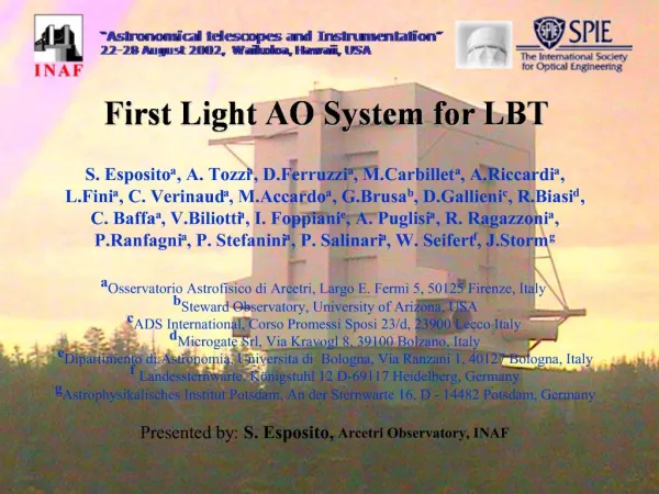
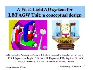
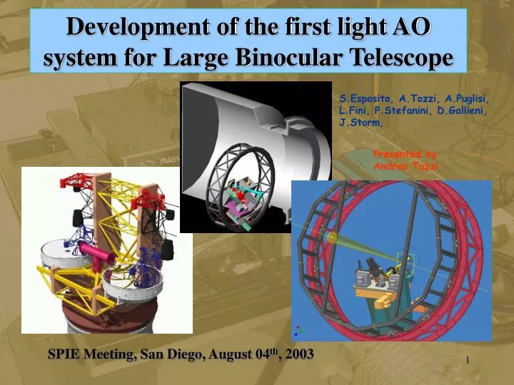
Development of the first light AO system for Large Binocular Telescope. S.Esposito, A.Tozzi, A.Puglisi, L.Fini, P.Stefanini, D.Gallieni, J.Storm,. Presented by Andrea Tozzi. SPIE Meeting, San Diego, August 04 th , 2003. Introduction.

E N D
Development of the first light AO system for Large Binocular Telescope S.Esposito, A.Tozzi, A.Puglisi, L.Fini, P.Stefanini, D.Gallieni, J.Storm, Presented by Andrea Tozzi SPIE Meeting, San Diego, August 04th, 2003
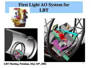
Introduction • The first light Adaptive Optic system for LBT is supposed to be ready in late summer 2004 • Location: front bent gregorian focus, into the Acquisition Guiding and Wavefront sensing unit (AGW) • Detailed design has been completed by the end of 2002 • Important modifications with respect SPIE 2002 • Laboratory tests and assembly in March 2003
The WFS into AGW AGW Auxiliary units WFS board Support structure
front view AGW flange plane Input LBT beam Z stage Lucifer window Y stage X stage WFS arrangment stages • Movable vs Fixed • Advantages: • Reduced size • Number and cost of • optical elements • High optical throughput • Minimiza non common path • aberrations • Reduce system • differential flexure • Reduce turbolence • Easy testing • Drawbacks: • System misalignement • and tilt due the • translation stages • Well centered structure • Reduced size • For central position FOV no exursion stage Front surface of Lucifer window center is at 27 mm from AGW flange
Telecentic lens 116 mm 116 mm (2.1,>1.3) (-1.1,>1.3) 86 mm 86 mm WFS alignment axis y y x x X stage Y stage (2.1,-1.0) (-1.1,-1.0) Working WFS FOV Exploring area: FOV in arcmin from the centre of the telecentric lens Scale f/15 = 36 mm/arcmin
The “new” AO WFS board before We have changed the optical arrangemnt of the T.V. and H.O. After: W shape!! • Linear stages position for • center FOV is centered • under the board • Better weight distribution on • the board • The board is well centered • around the AGW axis
Optical beams: W shape 320 mm Double Pyramid HO CCD Camera lens Lucifer Window Rirotator f15f45 triplet lens 400 mm ADC Tip Tilt Mirror LBT f15 focus Tech. Viewer CCD
ADS finite element analysis The model takes into account of: AGW, Lucifer, Bayside Stages, WFS, Off axis unit, Auxiliary units,... Load case definition:
elevation angle changes = • rotation angle changes = Flexure & displacement 0.86 µm (1h obs.) 0.50 µm (1h obs.) ADS FE analysis 1.0 µm (1h obs.) Maximum displacements for the mid point of the NGS board (Load case at EL= Zenith, ROT=0° is taken as reference) : ~107 asec 2.8 µm ~ 35 asec 0.9 µm Structure Stiffness Old configuration New configuration CCD image shifting in the worst load case Old Flexure & displacement • elevation angle changes = • rotation angle changes = 3.60 µm (1h obs.) 2.00 µm (1h obs.) ADS FE analysis 4.1 µm (1h obs.) New CCD39 pixel = 24 micron with NGS support structure fixed: ~ 34 asec 0.88 µm
WFS board Aerial view • Filter Wheel #1 (8 pos avaible): • 20/80 • 50/50 • 100/0 • LW/SW @ LW<600nm/SW<600nm • .......... (Trasmission H.O./T.V. Beam) Filter wheel #1 Top view Filter Wheel Tech. Viewer (8 pos avaible) Technical Viewer FOV: 10’’ X 10’’ (Zemax optical project) 7.4’’ X 7.4’’ (with Marconi CCD47 BI) Scale = 1.8 mm/” Filter wheel TV
WFS board tests Inventor Project • Standard Optical parts • (lens, mirrors…): ready! • (made by Silo - Italy) • Non standard Optical parts • (Double Pyramid): quite ready! • (made by INAF/INOA - Italy)
LBT simulated focus LBT simulator LBT “simulator” 100 mm WFS input beam: F/15 telecentric beam LBT simulated pupil (8 mm diameter)
Laboratory Optical tests Wavefront sensor board LBT beam simulator Rotational table
29.8 (-1.6,-1) (-1.5,0.2) 30.0 30.2 30.0 (-0.2,0.1) (0,0) First pupil images With preliminary single pyramid (BK7, angle 2°) ! • Pupil diameter: 30.0 – 30.2 – 30.0 – 29.8 pixel (720.0 - 724.8 - 720.0 - 715.2 micron) • Pupil center position max error: 0.5 pixel (12 micron) • Pupil stability vs gravity position (0 to 90 deg rotation) = 0.08 pixel rms in quadrature = 0.11 pixel (2.6 micron)
ideal pyramid scratched edges Measure of the energy collected into the four pupils vs modulation Dimension of the roof, the edge, energy loss ideal edges Pyramid quality • dimension of pyramid roof = 36 μm • dimension of pyramid edge = 15 μm energy loss = 20%-7% for modulation range ±4-±16 to increase goodness of optical polishing we are realizing a double pyramid sensor which needs bigger angles (about 30°) • Pupil center position error in pixel = (0;0) (-0.2;0.1)(-1.5;0.2)(-1.6;-1.0) due to a known mechanical allignment error of 2 arcmin
Wavefront sensor CCD and Electronics • Marconi EEV-39 deep depletion CCD • Electronic controller made by SciMeasure Inc. (Atlanta) • Real Time Electronics (RTC) by MicroGate (Italy) • Basic Computing Unit (BCU) by MicroGate (Italy) • readout noise about 9 e- • readout speed is 2.5 Mpixel/s for each quadrant • reduced readout speed (control electronics) • reduced readout noise and frame rate 1X1 binning (30X30 subap.) 2X2 binning (15X15 subap.) 650 fps (subap.=15X15) RON=3.2e- Dark current = 600 e-/s @-30° Agreement with EEV specifications !!
AO system supervisor • General setup (power-on, resident software downloading, ...) • Adjusting the otical devices (linear stages, fiter wheels,...) • Commanding the secondary mirror (open-loop operations) • Start/stop the cles loop operation • Acquisition of run-time diagnostic data and evaluation of loop quality parameters • Interaction qith the other components of the TCS • MsgD-RTDB: the message routing process and the Real Time Data Base • On-Ax.AGW ctrl: a process which control the WFS hardware, gest images, computed slopes from the Sloop Computer • AdSec ctrl: process which controls the Adaptive Secondary System hardware • UserInterface: used for engineering tasks (calibration, diagnostic,...). GUI interface, IDL procedures • TCS Interf: two processes which receive commands from TCS and provide status feedback to TCS (Intel base workstation running Linux OS)
conclusion • New arrangement of the stages assembly for positioning the wavefront sensor: • Reduced system flexure of more than a factor of three • pupil displacement is a small fraction of a subaperture • All WFS optical components has been acquired together with the majority of mechanical mounts • Initial tests on the wavefront sensor board: • pupil dimension is the nominal value (30 pixel) • Pupil displacements is negligeable (0.1 pixel) • positive initial tests on WFS CCD has been developed: RON • Control software architecture has been designed in detail and partly coded • Interface with TCS has been projected
Acknowledgement Roberto Ragazzoni Jesper Storm John Hill Walter Seifert Svend Bauer Piero Ranfagni Armando Ricacrdi Daniele Gallieni Roberto Biasi .........