Download
1 / 35
350 likes | 456 Views
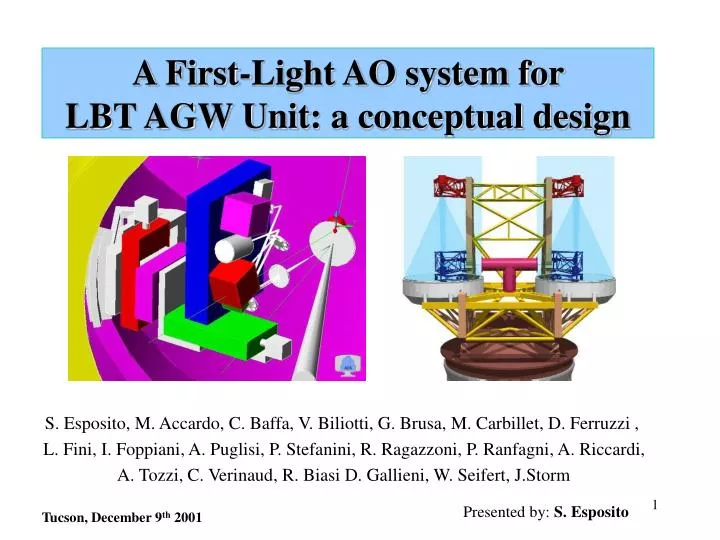
A First-Light AO system for LBT AGW Unit : a conceptual design. S. Esposito, M. Accardo, C. Baffa, V. Biliotti, G. Brusa, M. Carbillet, D. Ferruzzi , L. Fini, I. Foppiani, A. Puglisi, P. Stefanini, R. Ragazzoni, P. Ranfagni, A. Riccardi,

E N D
A First-Light AO system for LBT AGW Unit: a conceptual design S. Esposito, M. Accardo, C. Baffa, V. Biliotti, G. Brusa, M. Carbillet,D. Ferruzzi , L. Fini, I. Foppiani, A. Puglisi, P. Stefanini, R. Ragazzoni, P. Ranfagni, A. Riccardi, A. Tozzi, C. Verinaud, R. Biasi D. Gallieni, W. Seifert, J.Storm Presented by:S. Esposito Tucson, December 9th 2001
AO system for LBT AGW: Summary AO System Objectives The DM, Adaptive Secondary (LBT672) The WFS unit, pyramid sensor Real-Time loop control AO System Integration and Testing Time schedule, costs and manpower
System main Objectives • Very high correction with bright reference sources • High number of actuators 672 • High pupil sampling 32x32 (CCD39), 60x60 (CCD60) • Maximized Sky Coverage • High sensitivity of Pyramid Sensor • High transmittance of the WFS optics • no RON with CCD60
Adaptive secondary for LBT • 672 actuators • Tip-tilt and HO correction • Wavefront reconstructor on-board MMT Adaptive Secondary 911mm LBT AO System: DM
Reduce size, number and cost of optical elements • High optical throughput • Minimize NCP aberrations • Reduce system flexure • Reduce turbulence WFS optical path • Easy assembly and testing • the WFS unit • Same HO & TT reference star A Moveable WFS for the AGW unit 20th October 2001
LBT AO System: WFSs LGS (Sodium) WFS HO small 120x100x100 mm, 200mm refocuseable unit Instrument entrance window 15o F15 beam from LBT derotator unit NGS WFS HO&TT small 300x400mm,moveable unit acquiring +/- 60 arcsec FOV Instrument flange
A Moveable NGS WFS for the AGW F15 beam from LBT Instrument entrance window 15o NGS WFS HO&TT small 300x400mm moveable unit +/- 60 arcsec FOV derotator unit
Board misalignment Spot displacements on Pyramid vertex: 0.4mas/deg, J band FWHM 30mas Board translation Linear stages flexures: 15 mm traslation, 15 arcsec tilt Board tilt Spot displacements on Pyramid vertex: 0.1 mm, 0.05mas Pupil displacements onWFS CCD 0.5 mm/20 deg (24 mm/pixel)
Optical set-up Pyramid Optical set-up I
PSF Image plane Pupil plane The Pyramid Operating Principle Telescope pupil Glass Pyramid Pupil re-imager 4 3 DETECTOR 1 2 y pixels used for slope computation at the correspondin pupil subarea x
Board dimension 400x320 • mm including detectors • 100x100x100 CCD head • 80x100x100 STRAP unit A Moveable WFS for the AGW Unit II Incoming f15 beam from LBT focal plane HO beam TT beam Telecentric lens pyramids Field Viewer beam ADC optics Filter wheel CCD 39/60 Piezo steering mirror PI Field viewer Strap unit
Folding mirrors Filter wheels Another view........ Strap unit CCD39 Field viewer PI
Pupils on CCD 60 (128x128) Camera doublet f = 67 mm Focal plane to pupil plane distance 135mm Pupil diameter: 1440 mm (60 pixels) NGS High OrderChannel (EEV39) NOT TO SCALE
board on axis, Strehl ratio at the focal plane (f/45) vs. FOV ZENIT angle (°) -1 -0.5 0 0.5 1 0 0.962 0.966 0.967 0.966 0.962 35 0.919 0.927 0.934 0.938 0.941 69 0.913 0.923 0.934 0.945 0.953 NGS HOPSF: Board On-AxisI
Board 1 arcmin off axis, Strehl ratio at the focal plane (f/45) Vs. FOV ZENIT angle (°) -1 -0.5 0 0.5 1 0 0.798 0.799 0.796 0.791 0.787 35 0.706 0.709 0.711 0.712 0.711 69 0.725 0.742 0.756 0.768 0.778 LBT only (f15) LBT + board (f45) NGS HOPSF: Board Off-Axis
The NGS HO Pyramid design I v u • Vertex u 30°, SK10 • Vertex v 28.2°, SSK2 • FOV +/- 1 arcsec • Energy loss on edges < 10 % • Chromatism 0.9-3 mm at 0-69 deg • wl range (0.6 – 1.0 mm)
NGS Tip-TiltChannel NOT TO SCALE
Strap Unit NGS Tip-Tilt beam II 2 arcsec / 3.6 mm 2.55mm 123 mm • APD sensitive area 200 mm • APD separation adjustable • around 2.8 mm • Pyramid angle 30 deg (SSK2) • Chromatism about 30 mm
3L CCD 65 • Sensible area 11.5x8.6 mm • FOV 6.4x4.8 arcsec • Pixel size 20x30 mm • R band not well sampled NGS Field Viewer beam CCD65 camera NOT TO SCALE
LGS High Order Channel Sodium beacon Telecentric lens for NGS board 764 mm, (32 pixel) NOT TO SCALE
58mm 1800 mm LGS High Order Channel • Single pyramid (Silica) • Pyramid angle 7 deg • No edge problems LBT NGS focal plane LBT LGS Focal plane 15.9mm 12.8mm 764 mm
ADC Coating (812 nm Balzer Supertriolin 0.7%) C04-64 BAM23 6.4 mm 6.4 mm 0.993 1 0.993 ADC 4 surfaces glass-air 0.038 0.962 Triplet FK51 KZFSN5 F2 1.71 mm 1.71 mm 1.71 mm 0.9983 0.9989 0.9989 0.996 Triplet 2 surfaces glass-air 0.014 0.986 Beam splitter BK7 0.7 mm 1 1 Beam splitter 2 surfaces glass-air 0.05 0.95 Telecentric lens F_Silica 5 mm 1 1 Telecentric lens 2 surfaces glass-air 0.014 0.986 Doublet camera C04-64 BAM23 2.85 mm 3.2 mm 0.995 1 0.995 Doublet camera 2 surfaces glass-air 0.014 0.986 Pyramid SK10 SSK2 5.84 mm 5.55 mm 0.9975 0.9985 0.996 Pyramid 2 surfaces glass-air 0.014 0.986 Balzer Silflex-VIS Total transmission 0.98 Mirror1 0.98 Mirror2 0.98 Total NGS HO transmission 0.846 NGS HO Channel throughput Air/Glass trasmission Internal Glass Trasmission Pyramid Edge losses 10 % TOTAL TRASMISSION 0.83 * 0.9 = 75 %
WFSs on-board Opto-mechanics • FW1 • tilt: +/- 9’ => +/- 2mm PSF disp. • hole: focus disp. 1mm • hole: beam traslation (20deg) => 1mm • pupil disp. (1/8 relative disp.) • PI mirror, as FW1 HO HO CCD TT STRAP • FW2 • hole: beam translation (10deg) => 0.5mm • pupil disp. (1/20 relative disp.) FW CCD • HO FM • tilt: +/- 1deg => +/- 1 mm PSF disp. • tilt: 1’ => pupil disp. of 8.7 mm FW2 PI FW1 Folding mirrors • TT FM • tilt: +/- 1deg => < 2 mm PSF disp. • tilt: 1’ => pupil disp. of 7 mm • hole: beam traslation, (20deg) => 1mm • pupil disp. (1/8 relative disp.) Filter wheels
Board positioning for guide star acquisition Sodium laser channel And WFS Ref. Source acquisition Board focusing
CCD LBT AO System: RT operation & HW Reconstruction: (32x32x2)x672x2op: 27 ms WF rec. 107 Gflop/s (336DSP) 32x32x2x32bit 27 ms trasm. time 2.4 Gbit/s fiber link M2 crates High speed fiber link TCS 64x64x16bit 1ms 1Kframe/s (65Mbit/s) CCD39/50/60 96 PIO Slope computer Controller Diag. comp 16op/sensing subap. 32x32 subaperture 50 ms comp. time DSP op. rate 320 Mflops/s RS 232 APDs' TIP-TILT STRAP UNIT SENSOR
First light and MMT test LBT 1st light: 32x32 sub. (16bit/pixel) 1Kframe/s (CCD60) 32x32x2 slopes (32bit/slope) 2048x672 REC MATRIX MMT test: 16x16 sub. (16bit/pixel) 500frames/s (CCD39) 16x16x2 slopes (32bit/slope) 512x336 REC MATRIX
Optical bench bolted to the tube LBT AO System: test facility I LBT672 15m
M2 Test Interferometer focus LBT AO System: test facility II Test beam F1 Reflecting optics WFS unit Test interferometer “Instrument” 15o tilted entrance window
First Light AOPreliminary cost estimate First Light AO requires work on various subprograms: • AO Software • Basic loop SW • Housekeeping • Diagnostics • Self-optimization • User interface • TCS interface • Installation • AO WFS • Design • Prototyping • Lab Test • P45 Test • MMT Test? • Full Sys test • Installation • LLLCCD • Det. Proc. • “Fasti” test • LLL Controller • Prototype • LLL Controller • LBT 672 • Test Tower • P36’ test • P45 test • LBT 672 constr. • LBT 672 test • Full Sys test • Installation
Cost Summary • Wavefront Sensor + SW • First Unit 362k$ • Second unit 185k$ • Total WFS 547k$ • Adaptive secondary 136 K$ • Not charged to LBTC: • LLLCCD DEV 270k$ • Test Tower 185k$ • Total 455k$ 683 k$ LBTC cost 455 k$ Arcetri/Bologna cost
Work in progress…… Optical design optimization & tolerances Mechanical tolerances System performance simulations Rerotator, optical vs. software other................