Download

1 / 80
850 likes | 1.25k Views
CMOS Design Methodologies. The Design Problem. Source: sematech97. A growing gap between design complexity and design productivity. Design Methodology. Design process traverses iteratively between three abstractions: behavior, structure, and geometry

E N D
The Design Problem Source: sematech97 A growing gap between design complexity and design productivity
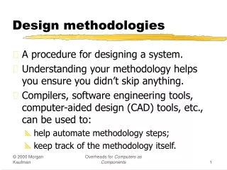
Design Methodology • Design process traverses iteratively between three abstractions: behavior, structure, and geometry • More and more automation for each of these steps
Design Analysis and Verification • Accounts for largest fraction of design time • More efficient when done at higher levels of abstraction - selection of correctanalysislevel can save multiple orders of magnitude in verification time • Two major approaches: • Simulation • Verification
Digital Data treated as Analog Signal Circuit Simulation Both Time and Data treated as Analog Quantities Also complicated by presence of non-linear elements (relaxed in timing simulation)
Circuit versus Switch-Level Simulation Circuit Switch
Design analysis and simulation • Spice - exact but time consuming • discrete time steps • circuit models • timing simulation with partitioning and relaxation method
Gate level simulation • faster than switch level • functional simulation • VHDL description used
Structural Description of Accumulator Design defined as composition of register and full-adder cells (“netlist”) Data represented as {0,1,Z} Time discretized and progresses with unit steps Description language: VHDL Other options: schematics, Verilog
Behavioral Description of Accumulator Design described as set of input-output relations, regardless of chosen implementation Data described at higher abstraction level (“integer”)
Behavioral simulation of accumulator Discrete time Integer data (Synopsys Waves display tool)
Design verification Electrical verification • checking number of inversions between two C2MOS gates • checking pull-up and pull down ratio in pseudo-NMOS gates • checking minimum driver size to maintain rise and fall times • checking charge sharing to satisfy noise-margins
Design verification Timing verification • Spice too long simulation time • RC delay estimated using Penfield-Rubinstein-Horowitz method • identification of critical path (avoid false paths)
Timing Verification Critical path Enumerates and rank orders critical timing paths No simulation needed! (Synopsys-Epic Pathmill)
Design verification • components described behaviorally • circuit model obtained from component models • resulting circuit behavior computed with design specifications • no generally acceptable verifier exists Formal verification
Custom circuit design • labor intensive • high time-to-market • cost amortized over a large volume • reuse as a library cell • was popular in early designs • layout editor, DRC, circuit extraction
Layout editor 1. Polygon based (Magic) 2. Symbolic layout • transistor symbols • relative positioning • compaction • stick diagram description • design rules automatically satisfied • automatic pitch matching
Custom Design – Layout Editor Magic Layout Editor (UC Berkeley)
Symbolic Layout • Dimensionless layout entities • Only topology is important • Final layout generated by “compaction” program Stick diagram of inverter
Design rule checking • on-line DRC - rules checked and errors flagged during layout • batch DRC - post design verification
Circuit extraction Circuit schematic derived from layout transistors are build with proper geometry parasitic capacitances and resistances evaluated extraction of inductance requires 3D analysis
Cell-based design • reduced cost • reduced time • reduced integrationdensity • reduced performance
Cell-based design • standard cell • compiled cells • module generators • macrocell place and route
Standard cell • library contains basic logic cells - inverter, AND/NAND, OR/NOR, XOR/NXOR, flip-flop - AOI, MUX, adder, compactor, counter, decoder, encoder, • fan-in and fan-out specified • schematic uses cells from library • layout automatically generated
Standard cell • cells have equal heights • cell rows separated by routing channels
Standard cell • large design cost amortized over a large number of designs • large number of different cells with different fan-ins • large fan-out for cells to be used in different designs • synthesis tools made standard cell design popular • standard cell design outperform PLA in area and speed • standard cell benefit from multi level logic synthesis
Compiled cell • cell layout generated on the fly • transistor or gate level netlist used with transistor size specified • layout densities approach that of human designers Circuit schematics with transistor sizing
Compiled cell Generated layout
Module generators • logic level cells not efficient for subcircuit design - shifters, adders, multipliers, data paths, PLAs, counters, memories • Macrocell generators - use design parameters like number of bits • data path compilers - use bit slice modules and repeat them N times - generate interconnections between modules
Datapath compilers Feedtroughs used to improve routing
Datapath compiler results Datapath compilers
Macrocell place and route • channel routing - metal 2 horizontal segments - metal 1 vertical segments • over the block routing (3-6 metal layers used)
Array-based design implementation • mask programmable arrays • fuse based FPGAs • nonvolatile FPGAs • RAM based FPGAs To avoid slow fabrication process which takes 3-4 weeks :
Mask programmable arrays • gate-array - similar to standard cell • sea-of-gate - routed over the cells (high density) - wires added to make logic gates • challenge in design is to utilize the maximum cell capacity • utilization < 75% for random logic design
Macrocell Design Methodology Macrocell Interconnect Bus Floorplan: Defines overall topology of design, relative placement of modules, and global routes of busses, supplies, and clocks Routing Channel
Macrocell-Based DesignExample SRAM SRAM Data paths Routing Channel Standard cells Video-encoder chip [Brodersen92]
Gate Array — Sea-of-gates Uncommited Cell Committed Cell(4-input NOR)
Sea-of-gate Primitive Cells Using oxide-isolation Using gate-isolation
Sea-of-gates Random Logic Memory Subsystem LSI Logic LEA300K (0.6 mm CMOS)
Prewired Arrays Categories of prewired arrays (or field-programmable devices): • Fuse-based (program-once) • Non-volatile EPROM based • RAM based
Programmable Logic Devices PAL PLA PROM
Fuse-based FPGA’s Actel sea-of-gate and standard cell approach