Download

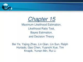
1 / 54
550 likes | 684 Views
CIRCUIT CHARACTERIZATION AND PERFORMANCE ESTIMATION CONTD……. Prof. N.S.Murthy, PPKKP/UNIMAP murthy@unimap.edu.my. 8/20/2014. EMT251_NSM_09. 1. V. DD. V. V. in. out. C. L. The CMOS Inverter: A First Glance. V. DD. CMOS Inverter. N Well. PMOS. 2 l. Contacts. Out. In. Metal 1.

E N D
CIRCUIT CHARACTERIZATION AND PERFORMANCE ESTIMATION CONTD…… Prof. N.S.Murthy, PPKKP/UNIMAP murthy@unimap.edu.my 8/20/2014 EMT251_NSM_09 1
V DD V V in out C L The CMOS Inverter: A First Glance
V DD CMOS Inverter N Well PMOS 2l Contacts Out In Metal 1 Polysilicon NMOS GND
Two Inverters Share power and ground Abut cells Connect in Metal
V V DD DD R p V out V out R n V V V 0 5 5 in DD in CMOS InverterFirst-Order DC Analysis VOL = 0 VOH = VDD VM = f(Rn, Rp)
V out V OH V M V in V OL V V IL IH Determining VIH and VIL A simplified approach
Gain=-1 Gain as a function of VDD
2.5 2 Good PMOS Bad NMOS 1.5 Nominal (V) out Good NMOS Bad PMOS V 1 0.5 0 0 0.5 1 1.5 2 2.5 V (V) in Impact of Process Variations
V DD PMOS Metal1 Polysilicon NMOS CMOS Inverters 1.2 m m =2l Out In GND
Transient Response ? tp = 0.69 CL (Reqn+Reqp)/2 tpHL tpLH
Design for Performance • Keep capacitances small • Increase transistor sizes • watch out for self-loading! • Increase VDD (????)
Device Sizing (for fixed load) Self-loading effect: Intrinsic capacitances dominate
NMOS/PMOS ratio tpHL tpLH tp b = Wp/Wn
Inverter Chain In Out CL • If CL is given: • How many stages are needed to minimize the delay? • How to size the inverters? • May need some additional constraints.
Inverter Delay • Minimum length devices, L=0.25mm • Assume that for WP = 2WN =2W • same pull-up and pull-down currents • approx. equal resistances RN = RP • approx. equal rise tpLH and fall tpHL delays • Analyze as an RC network 2W W tpHL = (ln 2) RNCL Delay (D): tpLH = (ln 2) RPCL Load for the next stage:
Inverter with Load Delay RW CL RW Load (CL) tp = kRWCL k is a constant, equal to 0.69 Assumptions: no load -> zero delay Wunit = 1
Inverter with Load CP = 2Cunit Delay 2W W Cint CL Load CN = Cunit Delay = kRW(Cint + CL) = kRWCint + kRWCL = kRW Cint(1+ CL /Cint) = Delay (Internal) + Delay (Load)
Example In Out CL= 8 C1 1 f f2 C1 CL/C1 has to be evenly distributed across N = 3 stages:
Optimum Number of Stages For a given load, CL and given input capacitance Cin Find optimal sizing f
Buffer Design N f tp 1 64 65 2 8 18 3 4 15 4 2.8 15.3 1 64 1 8 64 1 4 64 16 1 64 22.6 8 2.8
Vdd Vin Vout C L Dynamic Power Dissipation 2 Energy/transition = C * V L dd 2 Power = Energy/transition * f = C * V * f L dd Not a function of transistor sizes! Need to reduce C , V , and f to reduce power. L dd
How to keep Short-Circuit Currents Low? Short circuit current goes to zero if tfall >> trise, but can’t do this for cascade logic, so ...
Minimizing Short-Circuit Power Vdd =3.3 Vdd =2.5 Vdd =1.5
Leakage Sub-threshold current one of most compelling issues in low-energy circuit design!
Reverse-Biased Diode Leakage JS = 10-100 pA/mm2 at 25 deg C for 0.25mm CMOS JS doubles for every 9 deg C!
Static Power Consumption Wasted energy … Should be avoided in almost all cases, but could help reducing energy in others (e.g. sense amps)
Principles for Power Reduction • Prime choice: Reduce voltage! • Recent years have seen an acceleration in supply voltage reduction • Design at very low voltages still open question (0.6 … 0.9 V by 2010!) • Reduce switching activity • Reduce physical capacitance • Device Sizing: for F=20 • fopt(energy)=3.53, fopt(performance)=4.47
Goals of Technology Scaling • Make things cheaper: • Want to sell more functions (transistors) per chip for the same money • Build same products cheaper, sell the same part for less money • Price of a transistor has to be reduced • But also want to be faster, smaller, lower power
Technology Scaling • Goals of scaling the dimensions by 30%: • Reduce gate delay by 30% (increase operating frequency by 43%) • Double transistor density • Reduce energy per transition by 65% (50% power savings @ 43% increase in frequency • Die size used to increase by 14% per generation • Technology generation spans 2-3 years
Year of Introduction 1999 2000 2001 2004 2008 2011 2014 Technology node [nm] 180 130 90 60 40 30 Supply [V] 1.5-1.8 1.5-1.8 1.2-1.5 0.9-1.2 0.6-0.9 0.5-0.6 0.3-0.6 Wiring levels 6-7 6-7 7 8 9 9-10 10 Max frequency [GHz],Local-Global 1.2 1.6-1.4 2.1-1.6 3.5-2 7.1-2.5 11-3 14.9 -3.6 Max mP power [W] 90 106 130 160 171 177 186 Bat. power [W] 1.4 1.7 2.0 2.4 2.1 2.3 2.5 Technology Evolution (2000 data) International Technology Roadmap for Semiconductors Node years: 2007/65nm, 2010/45nm, 2013/33nm, 2016/23nm
Technology Scaling (1) Minimum Feature Size
Technology Scaling (3) tpdecreases by 13%/year 50% every 5 years! Propagation Delay
Technology Scaling (4) From Kuroda
mProcessor Scaling P.Gelsinger: mProcessors for the New Millenium, ISSCC 2001