Download
1 / 19
200 likes | 211 Views
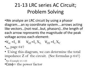
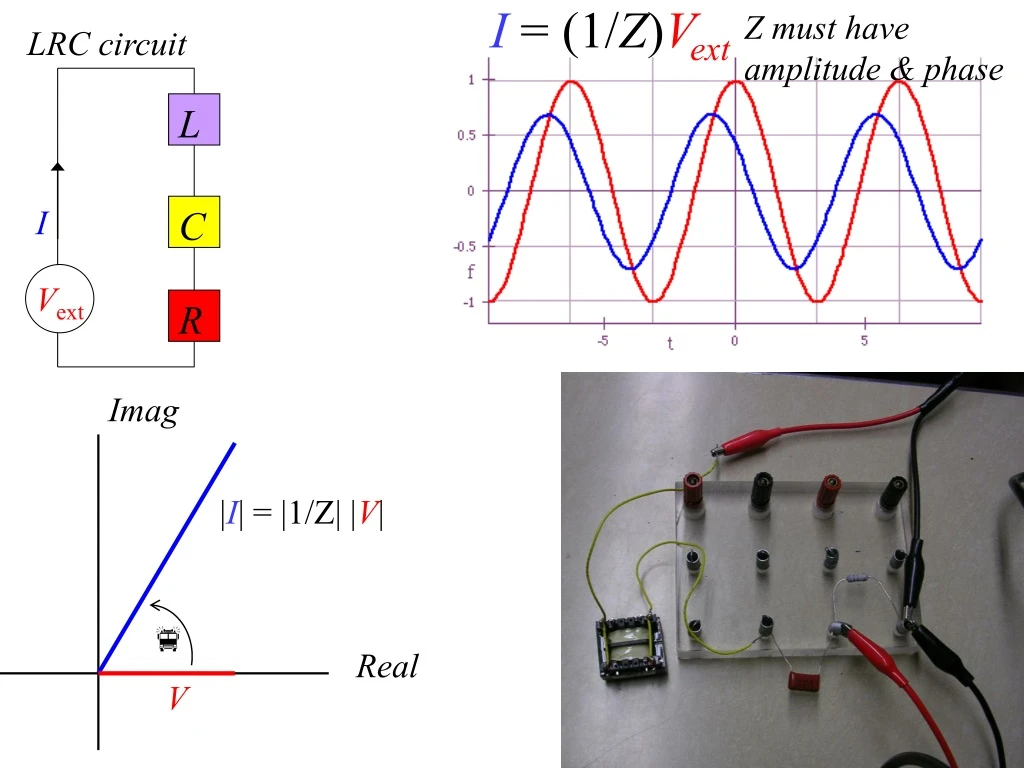
I = (1/ Z ) V ext. L. I. C. Imag. V ext. R. | I | = |1/Z| | V |. f. Real. V. Z must have amplitude & phase. LRC circuit. 1 /Z (also Y ) is ADMITTANCE Is a ratio of "out/in". Z is IMPEDANCE (generalized resistance). Usually write:.

E N D
I = (1/Z)Vext L I C Imag Vext R |I| = |1/Z| |V| f Real V Z must have amplitude & phase LRC circuit
1/Z (also Y) is ADMITTANCE Is a ratio of "out/in" Z is IMPEDANCE (generalized resistance) Usually write: But Z is ratio of applied voltage to resulting current, or "in/out" 1/Z is a frequency-dependent, complex quantity that describes the system's response to a driving voltage. It is a "response function".
Is there a phase shift? I V=IR Vext R Look for independent of w R circuit Purely resistive circuit: • Current in phase with driving voltage at all frequencies • Magnitude indep. of frequency
I V=IR Vext R R circuit drive response Phasor diagram Impedance, Z Admittance, 1/Z
I V=q/C Vext C Look for C circuit Purely capacitive circuit: • Current leads driving voltage (ICE) • Magnitude depends on frequency dependent on w
I V=q/C Vext C C circuit input output Phasor diagram ICE Impedance, Z Admittance, 1/Z (sometimes Y)
I + V Vext L - Look for dependent on w L circuit VL=LdI/dt Purely inductive circuit: • Current lags driving voltage (ELI) • Magnitude depends on frequency
I + V Vext L - L circuit input output Phasor diagram ELI Impedance, Z Admittance, 1/Z
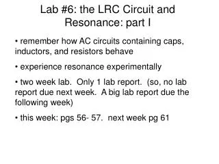
L I C R LRC circuit L (inductance), C (capacitance), cause oscillation, R (resistance) causes damping
I = (1/Z)V L I C Imag Vext R |I| = |1/Z| |V| f Real V LRC circuit
What is the best variable to plot for the LRC lab?ADMITTANCE Amplitude of I/Vapp Frequency, w ->
Phase of I (rel to Vapp) Frequency, w ->
large if b is small compared to w0 Q factor of an underdamped oscillator Damping time or "1/e" time is t = 1/b > 1/w0(>> 1/w0 if b is very small) How many T0 periods elapse in the damping time? This number (times π) is the Quality factor or Q of the system.
Max Amplitude Current Amplitude |I0| Driving Frequency------> Find frequencies where POWER drops to half maximum (current drops to 0.707 of max). These define . Find resonant frequency, 0 Homework problem to show the two definitions are the same.
QUETSION: FM radio stations have broadcast frequencies of approximately 100 MHz. Most radios use a series LRC circuit similar to the one you used in the lab as part of the receiver electronics. Estimate the spacing of the broadcast frequencies of FM stations if typical receivers have a Q of 500 or better. Explain your reasoning, and include a graph. station 1 station 2 Dw Dw
QUETSION: FM radio stations have broadcast frequencies of approximately 100 MHz. Most radios use a series LRC circuit similar to the one you used in the lab as part of the receiver electronics. Estimate the spacing of the broadcast frequencies of FM stations if typical receivers have a Q of 500 or better. Explain your reasoning, and include a graph. station 1 station 2 Dw Therefore, stations 99.3 and 99.5 FM are allowed, but 99.3 and 99.4 FM are not! They have cross-talk!
You should be able to: • Calculate & plot the magnitude and phase of 1/Z • Convert between the mag/phase and Re/Im forms • Draw phasor diagrams of Vext, I, 1/Z (or Z) • Express 1/Z (or Z) in terms of R, L, C or w0, b • You should be able to discuss: • The amplitude of the response and resonance • The phase of the response • The nature of the behavior at all frequencies • The transfer of the series LCR circuit analysis to analogous oscillatory systems