Download
1 / 11
110 likes | 273 Views
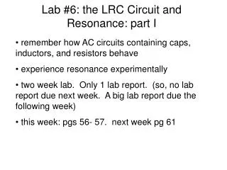
Lab #6: the LRC Circuit and Resonance: part I. remember how AC circuits containing caps, inductors, and resistors behave experience resonance experimentally two week lab. Only 1 lab report. (so, no lab report due next week. A big lab report due the following week)

E N D
Lab #6: the LRC Circuit and Resonance: part I • remember how AC circuits containing caps, inductors, and resistors behave • experience resonance experimentally • two week lab. Only 1 lab report. (so, no lab report due next week. A big lab report due the following week) • this week: pgs 56- 57. next week pg 61
LRC Circuit Phenomena of resonance an important one in physics • Impedence: • Resistor: • Capacitor: • Inductor: (voltage in phase with current) R (voltage lags current by 90o) (voltage leads current by 90o)
Current I is max when denominator is min: when wL=1/wC
Resonance Resonance
phases Phase of current (and thus voltage across R) with respect to V0 Phase shift between voltage across resistor and input is zero when at resonant frequency
phases Note that since VL leads by 90 degrees and Vc lags by 90 degrees, they are always out-of-phase by 180 degrees
IMPORTANT!!!!! Replace C-1 with Vary the input frequency using the following values: (f=f0x(0.1,0.5,0.9,1.0,1.1,1.5,1.9,2.3) For each value, record the amplitudes of V0 and VR as well as the frequency f and the phase shift phi (from the time shift of the peaks) between V0 and VR. Calculate XL=WL and XC=1/wC using the measured values for L and C.
Hints • part A1. 200 mH -> 100mH • Part A1. assume uncertainty on internal resistanc eof the wave for is 2 ohms. • C-1 at low frequency, wave form across inductor is ugly. Measure to the average over the “features”. So, need to use cursors, not “measure” • C-1 don’t assume V0 does not change, monitor it and check that it does not change • C-1 note phase shift changes sign. • C-3. don’t read off plot. Just extrapolate data linearly between the + and – shift point. • ditto for C-4
Step-wave input Like striking a bell with a hammer Charge on cap rings at resonant frequency while decaying away
At large R Critically damped: R is large enough so that no oscillation occurs
Hints: Part b Capture a wave form of the ringing with wavestar