Download
1 / 34
340 likes | 484 Views
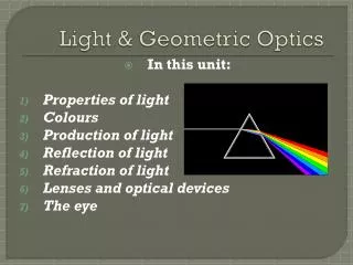
UNIT TWO LIGHT AND GEOMETRIC OPTICS Chapters 9 - 11. 9.1 What Is Light p. 326-328 Light is a form of energy that is visible to the human eye. It is one type of electromagnetic radiation. Electromagnetic Spectrum p. 326.

E N D
UNIT TWO LIGHT AND GEOMETRIC OPTICS Chapters 9 - 11
9.1 What Is Light p. 326-328 Light is a form of energy that is visible to the human eye. It is one type of electromagnetic radiation.
Electromagnetic radiation is composed of oscillating electric and magnetic fields.
Electromagnetic radiation sometimes behaves as a wave and sometimes behaves as a particle. In fact all energy and matter has this property. Heavy matter shows more of a particle nature while matter with very little mass shows its wave nature much easier.
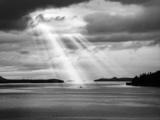
Light travels in straight lines (linear propagation). A ray is a straight line path taken by light energy. The speed of light in a vacuum is an important constant for our universe. c = 3.00 x 10⁸ m/s p. 328 1-4, 7 extra 5,6
9.2 Reflection and Formation of Images p.329-331 The Laws of Reflection hold for waves or particles of light. 1. The angle of incidence is equal to the angle of reflection (qi = qr). 2. The incident ray, the reflected ray and the normal ray all lie in the same plane. figure 1, p. 329
Images in a Plane Mirror Drawing an Image:Technique 1 object image observer mirror
Drawing an Image Technique 2 object image observer mirror don’t worry about eye on this one just draw any two light rays from object and reflect them
These are virtual images since the light rays appear to come from behind the mirror but in fact they do not. On the images worksheet complete the normal technique and the angle technique of plane mirrors.
9.3 THE REFRACTION OF LIGHT p.332-333 Refraction is the change in direction of waves as they pass from one medium into another. The change in speed from one medium to another causes the change in direction of the waves.
fast slow
9.4 Index of Refraction p.334-335 The index of refraction is defined as the ratio of the speed of light in a vacuum (c) to the speed of light in a given material (v). Since the speed of light is greatest in a vacuum the indexes of refraction are greater than one. See Table 1 p. 334 p. 335 1-3 purple, extra p. 335 1-5 blue
9.5 Laws of Refraction p. 336-338 1. The ratio of the sine of the angle of incidence to the sine of the angle of refraction is a constant (Snell’s Law). 2. The incident ray and the refracted ray are on opposite sides of the normal at the point of incidence , and all three are in the same plane. Snell’s Law
9.4 Index of Refraction p.334-335 The index of refraction is defined as the ratio of the speed of light in a vacuum (c) to the speed of light in a given material (v). Since the speed of light is greatest in a vacuum the indexes of refraction are greater than one. Larger n values means lower speeds of light. See Table 1 p. 334 p. 335 1-3, extra p. 335 1-5
9.5 Laws of Refraction p. 336-338 1. The ratio of the sine of the angle of incidence to the sine of the angle of refraction is a constant (Snell’s Law). 2. The incident ray and the refracted ray are on opposite sides of the normal at the point of incidence , and all three are in the same plane. Snell’s Law
n and sin q are inversely related. Large n (slow v) result in larger sin q (large q, bend away). Small n (large v) result in small sin q, bend towards. medium 1 q1 medium 2 q2
air la qa d lw qw water
Light travels from glass (1) into water (2). The index of refraction for glass is 1.52 and for water is 1.33. The angle of incidence in the glass is 40.0°. What is the angle of refraction in the water? n1 = 1.52 n2 = 1.33 θ1 = 40.0° θ2 = ? p. 338 1-3 p. 340 1-4 Refraction images on images worksheet
9.6 Total Internal Reflection p. 341-346 When light originates in an optically denser medium and passes into another some light is reflected and some is refracted. The re-fracted light is bent away from the normal. As the angle of incidence increases the intensity of reflected light increases while the intensity of the refracted light de-creases. When the angle of refraction be-comes ninety degrees the refracted ray ceases to exist and there is total internal reflection.
The critical angle is the incident angle in an optically denser medium at which total internal reflection occurs. In calculating the critical angle using Snell’s Law the refracted angle of 90o is utilized along with the indexes of refraction of the two media. If a second medium is not mentioned assume that the light is exiting to air.
What is the critical angle in water? The critical angle in water is 48.75o
p. 342 1-4 extra p. 345 1-5 read applications of total internal reflection p. 344-345 total internal reflection drawing p. 344 figure 8 and figure 9
Applying Total Internal Reflection Mirrors and Prisms Most metallic reflectors cannot completely reflect light as some is often absorbed into the material. Plane mirrors that are made through silvering the back of glass and sometimes produces additional images due to reflection from the front surface of the glass and the internal reflections in the glass.
To avoid some of these difficulties (multiple images, etc.) caused by front surface mirrors, total internal reflection prisms are employed. They are able to reflect nearly all of the light energy and their reflective surfaces won’t tarnish. An example of this is within binoculars.
Fibre Optics and Communication The concept of Total Internal Reflection is also applied in fibre optic cables and sending signals through them. The most basic optic fibre is a transparent glass or plastic rod. Depending upon the angle at which signals are sent through these rods, refracted rays and reflected rays will be present.
The cables are thus designed so that all of the signals stay within the cable regardless of the cable’s shape. Light energy is usually trapped.