Download
1 / 27
330 likes | 633 Views
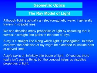
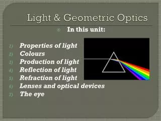
Light: Geometric Optics. Chapter 23. Ray Model of Light. Light Packet of light leaves an object and enters the eye Ray model is useful to predict how light works in some cases Ray model explains reflection, refraction, and image formation Geometric Lines and angles are involved.

E N D
Light: Geometric Optics Chapter 23
Ray Model of Light • Light • Packet of light leaves an object and enters the eye • Ray model is useful to predict how light works in some cases • Ray model explains reflection, refraction, and image formation • Geometric • Lines and angles are involved
Reflection • What happens when light hits a surface? • Absorbed, transmitted, reflected, or a combination of all three • Smooth surface • Angle of incidence (θi) = angle of refraction (θr) • Rough surface • Diffuse reflection • Brain interprets the rays having come from a straight line • Virtual image vs. real image Normal to Surface θr θi
Example • A woman 1.6 m tall stands in front of a vertical plane mirror. What is the minimum height of the mirror, and how high must its lower edge be above the floor if she is to be able to see her whole body? (Assume her eyes are 10 cm below the top of her head.)
Spherical Mirrors Convex • Convex • Bulge toward center • Produce a magnified image • Concave • Center bulges inward • Produce a demagnified image Concave
Spherical Mirrors Cont. • Focal point • Point where all parallel rays converge after being reflected • Focal length • Length from focal point to mirror • f = r/2 • f = focal length (m) • r = radius of curvature • Spherical aberration • More curvature to mirror creates a blurred image
Spherical Mirrors – Drawing • What if the object is significantly further away? • How do we determine where the image forms? • Draw 3 rays • Ray 1 – parallel to axis; goes through focal point • Ray 2 – goes from object through focal point; reflected parallel to axis • Ray 3 – perpendicular to the mirror surface so that it reflects back through the center of curvature • The image forms where the 3 rays cross • Image distance (I)
Spherical Mirrors – Mathematical • 1/f = 1/do + 1/di • f = focal length (m) • do = distance from object to mirror (m) • di = distance from image to mirror (m) • m = hi/ho = - di/do • m = magnification • ho = height of object (m) • hi = height of image (m)
Sign Conventions • Height • Positive if image is upright • Negative if image is inverted • Distance • Positive if on reflecting side of mirror • Negative if it is behind the mirror
Example • A 1 cm high object is placed 10 cm from a concave mirror whose radius of curvature is 30 cm. • Draw a ray diagram to locate the position of the image. • Determine the position of the image and the magnification analytically.
Example • An external rearview car mirror is convex with a radius of curvature of 16 m. Determine the location of the image and its magnification for an object 10 m from the mirror.
Index of Refraction • Speed of light in a vacuum • 2.99792458 E8 m/s ≈ 3E8 m/s • Speed in a medium is less than that of a vacuum • Index of Refraction (p. 642: Table 23-1) • Ratio of two speeds • n = c/v • n = index of refraction • c = speed of light in a vacuum (3E8 m/s) • v = speed of light in given medium (m/s)
Example • Calculate the speed of light in a diamond.
Refraction: Snell’s Law • Light strikes a surface • Part is reflected and part is transmitted • Transmitted ray is bent if at an angle • Snell’s Law or Law of Refraction • n1sinθ1 = n2sinθ2 Normal Incident Ray θi θr Refracted Ray
Example • Light traveling in air strikes a flat piece of uniformly thick glass at an incident angle of 60o. If the index of refraction of the glass is 1.5, • What is the angle of refraction in the glass? • What is the angle at which the ray emerges from the glass?
Total Internal Reflection • For a given angle of incidence, θc, the angle of refraction is 90o • Any angle of incidence less than that, some of the light is reflected and some is refracted • Any angle of incidence greater than that, all of the light is reflected back into the material • n1sinθc = n2sin90o • sinθc = n2/n1 • Uses • Prisms, fiber optics
Thin Lenses; Ray Tracing • Uses • Eyeglasses, cameras, and telescopes • Thickness is small compared to radius of curvature • Can be convex, concave, or a combination Double Convex Planoconvex Convex Meniscus Double Concave Planoconcave ConcaveMeniscus
Double Convex Lens • Assume index of refraction is greater than air (i.e., glass) • All incoming parallel rays will be focused at the focal point • Focal point is the same on both sides of the lens • Lenses thicker in the center will focus parallel light on the focal point and are converging lenses
Double Concave Lens • Lenses thinner in the center make parallel light diverge and are thus called diverging lenses • Focal point on a diverging lens is the point where the diverging rays, if traced in a straight line back through the lens would meet
Thin Lenses; Ray Tracing • Power • Optometrists use the reciprocal of the focal length to specify the power of the lens • P = 1/f • P = Power (Diopters) • f = focal length (m)
Thin Lenses; Ray Tracing • Finding the image for a thin lens • Converging Lens • Draw 3 rays • Ray 1 is parallel to the axis and passes through the focal point • Ray 2 passes through the focal point and emerges parallel to the axis • Ray 3 passes straight through the center of the lens
Thin Lenses; Ray Tracing • Finding the image for a thin lens • Diverging Lens • Draw 3 rays • Ray 1 is parallel to the axis and passes through the focal point (backtrack the ray to pass through the focal point) • Ray 2 is directed through the focal point on the opposite end and emerges parallel to the axis to the front of the lens • Ray 3 passes straight through the center of the lens
Thin Lens Equation: Magnification • Mathematical rather than drawing rays • Same as for mirror equations • 1/f = 1/do + 1/di • f = focal length (m) • do = distance from object to lens (m) • di = distance from image to lens(m) • m = hi/ho = - di/do • m = magnification • ho = height of object (m) • hi = height of image (m)
Thin Lens Equation; Magnification • Sign Conventions • The focal length is positive for converging lenses and negative for diverging lenses. • The object distance is positive if the object is on the side of the lens from which the light is coming; otherwise it is negative. • The image distance is positive if the image is on the opposite side of the lens from where the light is coming; if it is on the same side, di is negative. Real images have a positive image distance and virtual images have a negative image distance. • The height of the image, hi, is positive if the image is upright, and negative if the image is inverted relative to the object.
Example • What is the position and size of the image of a 7.6 cm high flower placed 1 m from a +50 mm focal-length camera lens?
Example • An object is placed 10 cm from a 15 cm focal-length converging lens. Determine the image position and size analytically and using a ray diagram.
Example • Where must a small insect be placed if a 25 cm focal-length lens is to form a virtual image 20 cm in front of the lens?