Download
1 / 37
370 likes | 561 Views
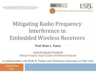
Kapil Gulati † , Aditya Chopra † , Robert W. Heath Jr . † , Brian L. Evans † , Keith R. Tinsley ‡ and Xintian E. Lin ‡ † The University of Texas at Austin ‡ Intel Corporation. MIMO Receiver Design in the Presence of Radio Frequency Interference. IEEE Globecom 2008.

E N D
Wireless Networking and Communications Group KapilGulati†, Aditya Chopra†, Robert W. Heath Jr. †, Brian L. Evans†, Keith R. Tinsley ‡ and Xintian E. Lin‡ †The University of Texas at Austin ‡ Intel Corporation MIMO Receiver Design in the Presence ofRadio Frequency Interference IEEE Globecom 2008
Problem Definition • Within computing platforms, wireless transceivers experience radio frequency interference (RFI) from clocks and busses. • Major sources of interference: • LCD clock harmonics • PCI Express busses • Our approach • Statistical modeling of RFI • Detection based on estimated model parameters • We consider a 2 x 2 MIMO system in presence of RFI We will use the terms noise and interference interchangeably Wireless Networking and Communications Group
Prior Work Wireless Networking and Communications Group
Proposed Contributions Wireless Networking and Communications Group
Bivariate Middleton Class A Model • Joint Spatial Distribution Wireless Networking and Communications Group
Results on Measured RFI Data • 50,000 baseband noise samples represent broadband interference Backup Marginal PDFs of measured data compared with estimated model densities Wireless Networking and Communications Group
System Model • 2 x 2 MIMO System • Maximum Likelihood (ML) Receiver • Log-Likelihood Function Sub-optimal ML Receivers approximate Wireless Networking and Communications Group
Sub-Optimal ML Receivers • Two-Piece Linear Approximation • Four-Piece Linear Approximation Approximation of chosen to minimize Wireless Networking and Communications Group
Results: Performance Degradation • Performance degradation in receivers designed assuming additive Gaussian noise in the presence of RFI • Simulation Parameters • 4-QAM for Spatial Multiplexing (SM) transmission mode • 16-QAM for Alamouti transmission strategy • Noise Parameters:A = 0.1, 1= 0.01, 2= 0.1, k = 0.4 Severe degradation in communication performance in high-SNR regimes Wireless Networking and Communications Group
Results: RFI Mitigation in 2 x 2 MIMO Improvement in communication performance over conventional Gaussian ML receiver at symbol error rate of 10-2 Communication Performance (A = 0.1, 1= 0.01, 2= 0.1, k = 0.4) Wireless Networking and Communications Group
Results: RFI Mitigation in 2 x 2 MIMO Complexity Analysis for decoding M-QAM modulated signal Complexity Analysis Communication Performance (A = 0.1, 1= 0.01, 2= 0.1, k = 0.4) Wireless Networking and Communications Group
Conclusions Backup Wireless Networking and Communications Group
Thank You, Questions ? Wireless Networking and Communications Group
References RFI Modeling [1] D. Middleton, “Non-Gaussian noise models in signal processing for telecommunications: New methods and results for Class A and Class B noise models”, IEEE Trans. Info. Theory, vol. 45, no. 4, pp. 1129-1149, May 1999. [2] K.F. McDonald and R.S. Blum. “A physically-based impulsive noise model for array observations”, Proc. IEEE Asilomar Conference on Signals, Systems& Computers, vol 1, 2-5 Nov. 1997. [3] K. Furutsu and T. Ishida, “On the theory of amplitude distributions of impulsive random noise,” J. Appl. Phys., vol. 32, no. 7, pp. 1206–1221, 1961. [4] J. Ilow and D . Hatzinakos, “Analytic alpha-stable noise modeling in a Poisson field of interferers or scatterers”, IEEE transactions on signal processing, vol. 46, no. 6, pp. 1601-1611, 1998. Parameter Estimation [5] S. M. Zabin and H. V. Poor, “Efficient estimation of Class A noise parameters via the EM [Expectation-Maximization] algorithms”, IEEE Trans. Info. Theory, vol. 37, no. 1, pp. 60-72, Jan. 1991 [6] G. A. Tsihrintzis and C. L. Nikias, "Fast estimation of the parameters of alpha-stable impulsive interference", IEEE Trans. Signal Proc., vol. 44, Issue 6, pp. 1492-1503, Jun. 1996 RFI Measurements and Impact [7] J. Shi, A. Bettner, G. Chinn, K. Slattery and X. Dong, "A study of platform EMI from LCD panels - impact on wireless, root causes and mitigation methods,“ IEEE International Symposium onElectromagnetic Compatibility, vol.3, no., pp. 626-631, 14-18 Aug. 2006 Wireless Networking and Communications Group
References (cont…) Filtering and Detection [8] A. Spaulding and D. Middleton, “Optimum Reception in an Impulsive Interference Environment-Part I: Coherent Detection”, IEEE Trans. Comm., vol. 25, no. 9, Sep. 1977 [9] A. Spaulding and D. Middleton, “Optimum Reception in an Impulsive Interference Environment Part II: Incoherent Detection”, IEEE Trans. Comm., vol. 25, no. 9, Sep. 1977 [10] J.G. Gonzalez and G.R. Arce, “Optimality of the Myriad Filter in Practical Impulsive-Noise Environments”, IEEE Trans. on Signal Processing, vol 49, no. 2, Feb 2001 [11] S. Ambike, J. Ilow, and D. Hatzinakos, “Detection for binary transmission in a mixture of Gaussian noise and impulsive noise modelled as an alpha-stable process,” IEEE Signal Processing Letters, vol. 1, pp. 55–57, Mar. 1994. [12] J. G. Gonzalez and G. R. Arce, “Optimality of the myriad filter in practical impulsive-noise environments,” IEEE Trans. on Signal Proc, vol. 49, no. 2, pp. 438–441, Feb 2001. [13] E. Kuruoglu, “Signal Processing In Alpha Stable Environments: A Least Lp Approach,” Ph.D. dissertation, University of Cambridge, 1998. [14] J. Haring and A.J. Han Vick, “Iterative Decoding of Codes Over Complex Numbers for Impulsive Noise Channels”, IEEE Trans. On Info. Theory, vol 49, no. 5, May 2003 [15] Ping Gao and C. Tepedelenlioglu. “Space-time coding over mimo channels with impulsive noise”, IEEE Trans. on Wireless Comm., 6(1):220–229, January 2007. Wireless Networking and Communications Group
Parameter Estimation Return • Parameter Estimator for Bivariate Middleton Class A model Moment Generating Function Wireless Networking and Communications Group
Parameter Estimation (cont…) Return Wireless Networking and Communications Group
Parameter Estimators Return Wireless Networking and Communications Group
Measured Fitting • Notes on measured RFI data • Radio used to listen to the platform noise only(when no data communication ongoing) • Noise assumed to be broadband • Do not expect bivariate Middleton Class A to fit perfectly • Expect bivariate Class A to model much better than Gaussian • Kullback-Leibler (KL) divergence Return Wireless Networking and Communications Group
Impact of RFI • Impact of LCD noise on throughput performance for a 802.11g embedded wireless receiver[Shi et al., 2006] Backup Wireless Networking and Communications Group
Impact of RFI • Calculated in terms of desensitization (“desense”) • Interference raises noise floor • Receiver sensitivity will degrade to maintain SNR • Desensitization levels can exceed 10 dB for 802.11a/b/g due to computational platform noise [J. Shi et al., 2006] Case Sudy: 802.11b, Channel 2, desense of 11dB • More than 50% loss in range • Throughput loss up to ~3.5 Mbps for very low receive signal strengths (~ -80 dbm) Return Wireless Networking and Communications Group
Assumptions for RFI Modeling • Key Assumptions [Middleton, 1977][Furutsu & Ishida, 1961] • Infinitely many potential interfering sources with same effective radiation power • Power law propagation loss • Poisson field of interferers • Pr(number of interferers = M |area R) ~ Poisson • Poisson distributed emission times • Temporally independent (at each sample time) • Limitations • [Alpha Stable]: Does not include thermal noise • Temporal dependence may exist Wireless Networking and Communications Group
[Middleton, 1999] Middleton Class A, B and C Models • Class A Narrowband interference (“coherent” reception)Uniquely represented by 2 parameters • Class B Broadband interference (“incoherent” reception)Uniquely represented by six parameters • Class C Sum of Class A and Class B (approx. Class B) Return Backup Wireless Networking and Communications Group
Parameter Description Range Overlap Index. Product of average number of emissions per second and mean duration of typical emission A [10-2, 1] Gaussian Factor. Ratio of second-order moment of Gaussian component to that of non-Gaussian component Γ [10-6, 1] Middleton Class A model • Probability Density Function PDF for A = 0.15,= 0.8 Wireless Networking and Communications Group
Middleton Class B Model • Envelope Statistics • Envelope exceedence probability density (APD), which is 1 – cumulative distribution function (CDF) Return Wireless Networking and Communications Group
Middleton Class B Model (cont…) • Middleton Class B Envelope Statistics Return Wireless Networking and Communications Group
Parameters Description Typical Range Impulsive Index AB [10-2, 1] Ratio of Gaussian to non-Gaussian intensity ΓB [10-6, 1] Scaling Factor NI [10-1, 102] Spatial density parameter α [0, 4] Effective impulsive index dependent on α A α [10-2, 1] Inflection point (empirically determined) εB > 0 Middleton Class B Model (cont…) • Parameters for Middleton Class B Model Return Wireless Networking and Communications Group
Symmetric Alpha Stable Model • Characteristic Function • Closed-form PDF expression only forα = 1 (Cauchy), α = 2 (Gaussian),α = 1/2 (Levy), α = 0 (not very useful) • Approximate PDF using inverse transform of power series expansion • Second-order moments do not exist for α < 2 • Generally, moments of order > α do not exist Backup PDF for = 1.5, = 0 and = 10 Backup Wireless Networking and Communications Group
Fitting Measured RFI Data • Broadband RFI data • 80,000 samples collected using 20GSPS scope Backup Distance: Kullback-Leibler divergence Wireless Networking and Communications Group
Fitting Measured RFI Data • Best fit for 25 data sets under different conditions Wireless Networking and Communications Group
Filtering and Detection Methods Middleton Class A noise Symmetric Alpha Stable noise Filtering • Wiener Filtering (Linear) Detection • Correlation Receiver (Linear) • MAP (Maximum a posteriori probability) detector[Spaulding & Middleton, 1977] • Small Signal Approximation to MAP detector[Spaulding & Middleton, 1977] Filtering • Myriad Filtering[Gonzalez & Arce, 2001] • Hole Punching Detection • Correlation Receiver (Linear) • MAP approximation Backup Backup Backup Backup Backup Wireless Networking and Communications Group
Results: Class A Detection Wireless Networking and Communications Group
Results: Alpha Stable Detection Backup Backup Use dispersion parameter g in place of noise variance to generalize SNR Wireless Networking and Communications Group
Performance Bounds (2x2 MIMO) • Channel Capacity [Chopra et al., submitted to ICASSP 2009] Return System Model Wireless Networking and Communications Group
Performance Bounds (2x2 MIMO) • Channel Capacity in presence of RFI for 2x2 MIMO[Chopra et al., submitted to ICASSP 2009] Return System Model Capacity Parameters:A = 0.1, G1 = 0.01, G2 = 0.1, k = 0.4 Wireless Networking and Communications Group
Performance Bounds (2x2 MIMO) • Probability of symbol error for uncoded transmissions[Chopra et al., submitted to ICASSP 2009] Return Pe: Probability of symbol error S: Transmitted code vector D(S): Decision regions for MAP detector Equally likely transmission for symbols Parameters:A = 0.1, G1 = 0.01, G2 = 0.1, k = 0.4 Wireless Networking and Communications Group
Performance Bounds (2x2 MIMO) • Chernoff factors for coded transmissions[Chopra et al., submitted to ICASSP 2009] Return PEP: Pairwise error probabilityN: Size of the codewordChernoff factor:Equally likely transmission for symbols Parameters:G1 = 0.01, G2 = 0.1, k = 0.4 Wireless Networking and Communications Group