Download
1 / 43
430 likes | 726 Views
Fluid Dynamic Aspects of Thin Liquid Film Protection Concepts S. I. Abdel-Khalik and M. Yoda. ARIES Town Meeting (Ma y 5-6, 2003). G. W. Woodruff School of Mechanical Engineering Atlanta, GA 30332 – 0405 USA. Overview. Thin liquid protection (Prometheus) Major design questions

E N D
Fluid Dynamic Aspects of Thin Liquid Film Protection ConceptsS. I. Abdel-Khalik and M. Yoda ARIES Town Meeting (May 5-6, 2003) G. W. Woodruff School of Mechanical Engineering Atlanta, GA 30332–0405 USA
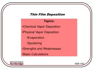
Overview Thin liquid protection (Prometheus) • Major design questions • “Wetted wall”: low-speed normal injection through porous surface • Numerical simulations • Experimental validations • “Forced film”: high-speed tangential injection along solid surface • Experimental studies
Thin Liquid Protection Major Design Questions • Can a stable liquid film be maintained over the entire surface of the reactor cavity? • Can the film be re-established over the entire cavity surface prior to the next target explosion? • Can a minimum film thickness be maintained to provide adequate protection over subsequent target explosions? Study wetted wall/forced film concepts over “worst case” of downward-facing surfaces
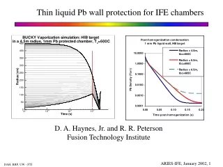
Wetted Wall Concept--Problem Definition Prometheus: 0.5 mm thick layer of liquid lead injected normally through porous SiC structure Liquid Injection First Wall ~ 5 m X-rays and Ions
Quantify effects of • injection velocity win • initial film thickness zo • Initial perturbation geometry & mode number • inclination angle • Evaporation & Condensation at the interface on • Droplet detachment time • Equivalent droplet diameter • Minimum film thickness prior to detachment Numerical Simulation of Porous Wetted Walls Summary of Results Obtain Generalized Charts for dependent variables as functions of the Governing non-dimensional parameters
Numerical Simulation of Porous Wetted WallsWetted Wall Parameters • Length, velocity, and time scales : • Nondimensional drop detachment time : • Nondimensional minimum film thickness : • Nondimensional initial film thickness : • Nondimensional injection velocity :
Water Lead Lithium Flibe T (K) 293 323 700 800 523 723 773 873 973 l (mm) 2.73 2.65 2.14 2.12 8.25 7.99 3.35 3.22 3.17 U0(mm/s) 163.5 161.2 144.7 144.2 284.4 280.0 181.4 177.8 176.4 t0 (ms) 16.7 16.4 14.8 14.7 29.0 28.6 18.5 18.1 18.0 Re 445 771.2 1618 1831 1546 1775 81.80 130.8 195.3 Numerical Simulation of Porous Wetted Walls Non-Dimensional Parameters For Various Coolants
Numerical Simulation of Porous Wetted Walls Effect of Initial Perturbation • Initial Perturbation Geometries Sinusoidal zo s Random zo Saddle zo s
mf+=-0.005 mf+=0.0 mf+=0.01 (Evaporation) (Condensation) *=31.35 *=27.69 *=25.90 Numerical Simulation of Porous Wetted Walls Effect of Evaporation/Condensation at Interface • zo*=0.1, win*=0.01, Re=2000
Numerical Simulation of Porous Wetted WallsDrop Detachment Time
Numerical Simulation of Porous Wetted WallsMinimum Film Thickness
Numerical Simulation of Porous Wetted Walls Evolution of Minimum Film Thickness (High Injection/Thick Films) Nondimensional Initial Thickness, zo*=0.5 Nondimensional Injection velocity, win*=0.05 Nondimensional Minimum Thickness Drop Detachment Minimum Thickness Nondimensional Time
Numerical Simulation of Porous Wetted Walls Evolution of Minimum Film Thickness (Low Injection/Thin Films) Nondimensional Initial Thickness, zo*=0.1 Nondimensional Injection velocity, win*=0.01 Nondimensional Minimum Thickness Drop Detachment Minimum Thickness Nondimensional Time
Numerical Simulation of Porous Wetted Walls Equivalent Detachment Diameter
J B I H C A F G E D Experimental Validations A Porous plate holder w/adjustable orientation B Constant-head plenum w/adjustable height C Sub-micron filter D Sump pump E Reservoir F CCD camera G Data acquisition computer H Plenum overflow line I Flow metering valve J Flexible tubing K Laser Confocal Displacement Meter K
Experimental Measurement -- “Unperturbed” Film Thickness Target Plate Water 20 ◦C win = 0.9 mm/s = 0◦ Mean Liquid Film Thickness = 614.3 m Standard Deviation = 3.9 m 10 mm Laser Sensor Head Laser Confocal Displacement Meter KEYENCE CORPORATION OF AMERICA, Model # : LT-8110
Experimental Variables • Experimental Variables • Plate porosity • Plate inclination angle • Differential pressure • Fluid properties • Independent Parameters • Injection velocity, win • “Unperturbed” film thickness, zo • DependentVariables • Detachment time • Detachment diameter • Maximum penetration depth
Experiment #W090 -- “Unperturbed” Film Thickness Liquid Film Thickness [m] +2 -2 • Water 20oC, win = 0.9 mm/s, = 0o • Mean Liquid Film Thickness = 614.3 m • Standard Deviation = 3.9 m Time [sec]
Experiment #W090 -- Droplet Detachment Time Number Fraction • Water 20oC, win = 0.9 mm/s, = 0o • Mean Droplet Detachment Time = 0.43 s • Standard Deviation = 0.04 s • Sample Size = 100 Droplets Droplet Detachment Time [sec]
Numerical Model Experiment Experiment #W090 -- Calculated Detachment Time Detachment Time [sec] +2 Mean Experimental value = 0.43 s -2 Normalized Initial Perturbation Amplitude, s/zo
Experiment #W090 -- Equivalent Droplet Detachment Diameter Number Fraction • Water 20oC, win = 0.9 mm/s, = 0o • Mean Droplet Diameter = 7.69 mm • Standard Deviation = 0.17mm • Sample Size = 100 Droplets Equivalent Droplet Diameter [mm]
Numerical Model Experiment Experiment #W090 – Equivalent Detachment Diameter Equivalent Droplet Diameter [mm] +2 Mean Experimental value = 7.69 mm -2 Normalized Initial Perturbation Amplitude, s/zo
Experiment #W090 -- Maximum Penetration Distance Number Fraction • Water 20oC, win = 0.9 mm/s, = 0o • Maximum Mean Penetration Depth = 55.5 mm • Standard Deviation = 5.1 mm • Sample Size = 100 Droplets Maximum Penetration Depth [mm]
Numerical Model Experiment Experiment #W090 -- Calculated Penetration Distance Maximum Penetration Depth [mm] +2 Mean Experimental value = 55.5 mm -2 Normalized Initial Perturbation Amplitude, s/zo
Experiment Simulation Experiment #W090 -- Evolution of Maximum Penetration Distance Penetration Depth [mm] Time [sec]
Wetted Wall Summary • Developed general nondimensional charts applicable to a wide variety of candidate coolants and operating conditions • Stability of liquid film imposes • Lower bound on repetition rate (or upper bound on time between shots) to avoid liquid dripping into reactor cavity between shots • Lower bound on liquid injection velocity to maintain minimum film thickness over entire reactor cavity required to provide adequate protection over subsequent fusion events • Model Predictions are closely matched by Experimental Data
Forced Film Concept -- Problem Definition Prometheus: Few mm thick Pb “forced film” injected tangentially at >7 m/s over upper endcap Injection Point ~ 5 m First Wall X-rays and Ions Detachment Distance xd Forced Film
Contact Angle, LS Glass : 25o Coated Glass : 85o Stainless Steel : 50o Plexiglas : 75o Forced Film Parameters • Weber number We • Liquid density • Liquid-gas surface tension • Initial film thickness • Average injection speed U • Froude number Fr • Surface orientation ( = 0° horizontal surface) • Mean detachment length from injection point xd • Mean lateral extent W • Surface radius of curvature R = 5 m • Surface wettability: liquid-solid contact angle LS • In Prometheus: for = 0 – 45, Fr = 100 – 680 over nonwetting surface (LS = 90)
Experimental Apparatus A Flat or Curved plate (1.52 0.40 m) B Liquid film C Splash guard D Trough (1250 L) E Pump inlet w/ filter F Pump G Flowmeter H Flow metering valve I Long-radius elbow J Flexible connector K Flow straightener M L I Adjustable angle J K x A z B H gcos g G C L Film nozzle M Support frame D E F
5 cm x y z A B C Liquid Film Nozzles • Fabricated with stereolithography rapid prototyping • A = 0.1 cm; B = 0.15 cm; C = 0.2 cm • 2D 5th order polynomial contraction along z from 1.5 cm to • Straight channel (1 cm along x) downstream of contraction
Experimental Parameters • Independent Variables • Film nozzle exit dimension = 0.1–0.2 cm • Film nozzle exit average speed U0 = 1.9 – 11.4 m/s • Jet injection angle = 0°, 10°, 30° and 45o • Surface inclination angle ( = ) • Surface curvature (flat or 5m radius) • Surface material (wettability) • DependentVariables • Film width and thickness W(x), t(x) • Detachment distance xd • Location for drop formation on free surface
Detachment Distance 1 mm nozzle 8 GPM 10.1 m/s 10° inclination Re = 9200
xd / vs.Fr: Wetting Surface • Water on glass: LS = 25o • xd increases linearly w/Fr • xd as • xd as =1 mm1.5 mm2 mm = 0 = 10 = 30 = 45 xd / Design Window: Wetting Surface Fr
xd /: Wetting vs. Nonwetting • Wetting: glass; LS =25o • Nonwetting: coated glass; LS = 85o • Nonwetting surface smaller xd, orconservative estimate • xd indep. of Open symbols Nonwetting Closed symbols Wetting =1 mm =1.5 mm • = 2 mm = 0 xd / Design Window Fr
xd: Wetting vs. Nonwetting =1 mm 1.5 mm 2 mm = 0 • Wetting: glass ( = 25°) • Nonwetting: Rain-X® coated glass ( = 85°) xd [cm] Glass Rain-X® coated glass We
Effect of Inclination Angle(Flat Glass Plate) =1 mm 1.5 mm 2 mm xd [cm] = 0 = 10 = 30 We
Detachment Distance Vs. Weber Number = 0 = 1 mm xd [cm] Glass(LS=25o) Stainless Steel(LS=50o) Plexiglas (LS=75o) Rain-X® coated glass (LS=85o) We
Effect of Weber Number on Detachment Distance(Flat and Curved Surfaces, Zero Inclination) =1 mm1.5 mm2 mm = 0 xd [cm] Flat Curved Plexiglas (LS = 70°) We
Effect of Inclination Angle(Curved Plexiglas) =1 mm1.5 mm2 mm • Curved nonwetting surface: Plexiglas ( = 70°); R = 5 m • xd as • xd as We • xd values at = 0° “design window” xd [cm] = 0 = 10 = 30 We
W/Wo: Wetting vs. Nonwetting Wetting (LS = 25o) • Marked lateral growth (3.5) at higher Re Nonwetting (LS = 85o ) • Negligible lateral spread • Contact line “pinned” at edges? • Contracts farther upstream = 2 mm = 0 Re = 3800 15000 W/Wo x/ Open Nonwetting Closed Wetting
y y x x Cylindrical Dams • In all cases, cylindrical obstructions modeling protective dams around beam ports incompatible with forced films • Film either detaches from, or flows over, dam y x
Forced Film Summary • Design windows for streamwise (longitudinal) spacing of injection/coolant removal slots to maintain attached protective film • Detachment length increases w/Weber and Froude numbers • Wetting chamber first wall surface requires fewer injection slots than nonwetting surface wetting surface more desirable • Cylindrical protective dams around chamber penetrations incompatible with effective forced film protection • “Hydrodynamically tailored” protective dam shapes
Acknowledgements Georgia Tech • Academic Faculty : Damir Juric • Research Faculty : D. Sadowski and S. Shin • Students : F. Abdelall, J. Anderson, J. Collins, S. Durbin, L. Elwell, T. Koehler, J. Reperant and B. Shellabarger DOE • W. Dove, G. Nardella, A. Opdenaker ARIES-IFE Team LLNL/ICREST • R. Moir