Download
1 / 15
150 likes | 163 Views
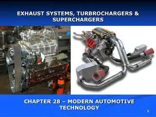
Maximization of Flow through Intake & Exhaust Systems. P M V Subbarao Professor Mechanical Engineering Department. Use Complex Wave Gas Dynamics for effective breathing…. Acoustic Theory of Piping.

E N D
Maximization of Flow through Intake & Exhaust Systems P M V Subbarao Professor Mechanical Engineering Department Use Complex Wave Gas Dynamics for effective breathing….
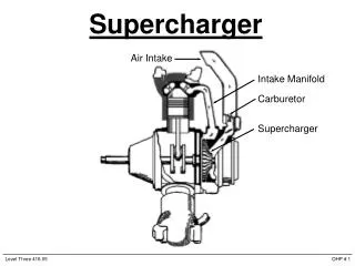
Acoustic Theory of Piping • The intake manifold to an internal combustion (IC) engine will consist of a network of interconnecting pipes. • The lengths of these pipes, and to a certain extent their diameters, must be chosen carefully as they will determine the resonant frequencies of the manifold. • When the engine is run at a speed where one or more of these resonances is excited, then both the volumetric efficiency and the intake noise level maybe affected.
Acoustic Modeling of Complex Piping System Induction System Model
Build Considerations for Resonating Piping System • Variable Length Runners for RPM matching • Materials Selection Criteria: • Weight, Fabrication, Surface Finish, Heat Isolation • Intake placement • Isolate from heat sources (Engine, Exhaust, Radiator, Pavement) • Fuel Injector Placement
Experimental Methods to Understand Resonant Frequencies of Induction System
Junctions The most complex cause of pressure waves is when the intake valve closes. Any velocity left in the intake port column of air will make high pressure at the back of the valve. This high pressure wave travels toward the open end of the intake tract and is reflected and inverted as a low pressure wave.
Central Theorem for Acoustic Design • The tuning peak will occur when the natural Helmholtz resonance of the cylinder and runner is about twice the piston frequency. • The Engine can generate highest Torque at turning peak conditions. • The aim of acoustic design is to achieve tuning peak at highest speed or highest power conditions. • Tuned port simply means that the intake runners are tuned to have highest volumetric efficiency at specific rpm range.
Acoustic Characterization of Components Using Engelman's electrical analogy we can define the system as a system defined by capacitances and inductances.
Acoustic Modeling of Runner Ideal Helmholtz Resonator: The theory behind what happens in the intake (and exhaust systems) is called A Helmholtz Resonator. Induction pressure waves can have an effect on how well the cylinders are filled. It can help (or hurt) power in a narrow rpm Range.
Determination of Primary Capacitance • The Primary Volume is considered to be the Cylinder Volume with the Piston at mid-stroke (effective volume). • Writing Clearance Volume in Terms of Compression Ratio:
Acoustic Modeling of Runner with Port • For a single degree of freedom system A1 = Average Area of Runner and Port L1 = LPort + Lrunner K1 = 642 C = Speed of Sound
Primary & Secondary Induction Systems • The prime system responsible for flow of air is called as primary system. • The remaining part of the system, which is not actively feed the cylinder is called as secondary system.