Download
1 / 49
540 likes | 1.05k Views
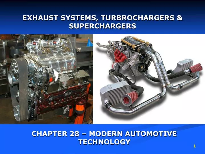
EXHAUST SYSTEMS, TURBROCHARGERS & SUPERCHARGERS. CHAPTER 28 – MODERN AUTOMOTIVE TECHNOLOGY. EXHAUST SYSTEM. Purpose: Quiets engine operation and carries exhaust fumes to the rear of the vehicle. EXHAUST SYSTEM. Typical Parts: Exhaust manifold Header pipe Catalytic converter

E N D
EXHAUST SYSTEMS, TURBROCHARGERS & SUPERCHARGERS CHAPTER 28 – MODERN AUTOMOTIVE TECHNOLOGY
EXHAUST SYSTEM Purpose: Quiets engine operation and carries exhaust fumes to the rear of the vehicle
EXHAUST SYSTEM Typical Parts: Exhaustmanifold Headerpipe Catalytic converter Intermediate pipe Muffler Tailpipe Hangers Heat shields Exhaust system clamps
EXHAUST SYSTEM Typical Parts: Exhaustmanifold connects the cylinder head exhaust ports to header pipe. Headerpipe steel tubing that carries exhaust gases from the exhaust manifold to the catalytic converter. Catalytic converter Device that removes pollutants from engine exhaust.
EXHAUST SYSTEM Typical Parts: Intermediate pipe Tubing sometimes used between the header pipe and muffler or catalytic converter and muffler Muffler Metal chamber for damping pressure pulsations to reduce exhaust noise Tailpipe Tubing that carries exhaust from the muffler to the rear of the car body
EXHAUST SYSTEM Typical Parts: Hangers Device for securing the exhaust system to the underside of the car body Heat shields metal plates that prevent exhaust heat from transferring into another object Exhaust system clamps U-bolts for connecting parts of the exhaust system together.
EXHAUST SYSTEM Exhaust Back Pressure: Pressure developed in the exhaust system Low Back Pressure = More efficient, well designed system High Back Pressure = Reduction of engine power Factors that create/limit back pressure: Size of exhaust pipes, Catalytic converter, Muffler
EXHAUST SYSTEM Single vs. Dual Exhaust: Single Exhaust System Most common – One pipe for exhaust gases to travel in from the engine to the rear of the vehicle. Used on small 4 cylinder and large V8 engines Dual Exhaust System Two separate pipes for exhaust gases to travel through reduced back pressure by letting the engine breathe better at high RPM. Used on performance V6 and V8 engines Crossover Pipe connects the right & left header pipes to equalize back pressure in a dual system to increase power.
EXHAUST SYSTEM Exhaust manifold heat valve: (heat control valve or heat riser) Forces hot exhaust gas to flow into the intake manifold to aid cold weather starting. Located in the outlet of the exhaust manifold A heat sensitive spring or a vacuum diaphragm and temperature sensing vacuum switch operate the butterfly valve. Engine cold – Valve closed increasing back pressure forcing hot gases into the exhaust passage of the intake manifold warming the floor of the manifold to hasten fuel vaporization. Engine warm – valve open allowing gases to flow through exhaust system normally.
EXHAUST SYSTEM Exhaust system service: Usually needed when a component in the system rusts and begins to leak. Engine combustions produces water and acids that deteriorate the exhaust components. Leaking exhaust systems can allow harmful fumes to enter the passenger compartment. CARBON MONOXIDE
EXHAUST SYSTEM Exhaust system repairs: Faulty parts can be removed and replaced. Rust penetrant should be used on all fasters that are going to be re-used in order to remove them in the best condition as possible. Removal of parts can be done with many tools: Air Chisel Hand chisel / Hammer Cutting torch Hacksaw Ratchet / Sockets (normally 14mm socket) Exhaust pipe cutter (chain style) Cut off tool (sawz-all) Always wear safety glasses to prevent rust and dirt from entering eyes.
EXHAUST SYSTEM Exhaust system repairs: Pipe expanders can be used on new pipe or old pipes to make new parts fit better if needed. A pipe shaper can be used to straighten pipe ends that are bent or dented. Position all clamps properly making sure it is clamping both pipes together (1/8” from end of outside pipe). Install any necessary adapters, hangers. Double check the system routing, does it have adequate clearance from the vehicles body and chassis?
EXHAUST SYSTEM Stainless Steel Exhaust system repairs: Use heavy duty clamps – regular clamps do not have enough clamping force to properly seal stainless tubing. When cutting stainless use the correct rod or wire material. Stainless steel does not react the same as carbon steel when heated near its melting point. Stainless can be “RED HOT” when it LOOKS COLD
EXHAUST SYSTEM Parts of the muffler:
TURBOCHARGERS An exhaust driven fan or blower that forced air into the engine under pressure. Increase power output Can improve engine efficiency
TURBOCHARGERS Parts: Turbine wheel – exhaust driven fan that turns the turbo shaft and compressor wheel. Turbine housing – outer enclosure that routes exhaust gases around the turbine wheel. Turbo shaft – steel shaft that connects the turbine and compressor wheels. It passes through the center of the bearing housing.
TURBOCHARGERS Parts: Compressor wheel – driven fan that forces air into the engine intake manifold under pressure Compressor housing – part of the turbo housing that surrounds the compressor wheel. Its shape helps pump air into the engine. Bearing housing – enclosure around the turbo shaft that contains bearings, seals, and oil passages.
TURBOCHARGERS Operation: Exhaust gases expelled from engine enter the turbine housing, pass over the turbine wheel and exit out the exhaust system. As the Engine RPM increases the turbine spins faster. Turbine is connected to the compressor wheel by the turbo shaft causing the compressor wheel to spin. As the compressor wheel spins it draws air into the compressor housing. Centrifugal pressure causes the air to be thrown out of the turbo and into the engine under pressure.
TURBOCHARGERS Location: Usually on one side of the engine as close to manifold as possible to ensure gases are still expanding to help spin the turbine increasing boost pressure and engine power. Exhaust pipes connect manifold(s) to turbine housing. Header pipes connect to the exit of the turbine housing. Blow through turbo system: Turbo located before the carburetor or throttle body, compressor wheel only compresses air, fuel enters after turbo. Draw-through turbo system: Turbo located after carburetor or throttle body, compressor wheel draws in both air and fuel on carburetor and throttle body injection systems. Port injection systems turbo will only pressurized air.
TURBOCHARGERS Lubrication:
TURBOCHARGERS Lubrication: Needed to protect the turbo shaft and bearings from damage Turbochargers can operate at speeds of up to 100,000 RPM – Engine lubrication system must force engine oil into the turbo shaft bearings Oil passages are provided in the turbo housing and bearings. An oil supply line runs from the engine to the turbo. With the engine running oil enters the turbo under pressure. Sealing rings are placed around the turbo shaft at each end of the turbo housing to prevent oil leakage into the compressor and turbine housings. A drain passage and drain line allow oil to return to the oil pan after passing through the turbo bearings.
TURBOCHARGERS Turbo Lag: A short delay before the turbo develops sufficient boost (pressure above atmospheric pressure) to meet engine demands. As the driver presses on the accelerator pedal it takes a small amount of time before the engine creates enough exhaust gases to spin the turbine and compressor wheels fast enough to develop boost. The vehicle may lack power for a second or two during Lag time. Modern engines suffer from lag very little compared to older turbo designs as they are made with lighter materials that take less force to spin. Carbon fiber enforced plastic impellers are used to cut weight and reduce lag.
TURBOCHARGERS Intercoolers:
TURBOCHARGERS Intercoolers: An air-to-air heat exchanger that cools the air entering the engine. Radiator like device mounted at the pressure outlet of the turbo or supercharger. When air is compressed its temperature rises, since hot air contains less energy-providing oxygen by volume, it will produce less power. A cooler charge of air is denser and can be mixed with more fuel to increase combustion and engine power. Outside air flows over and cools the fins and tubes of the intercooler removing heat from the air inside the tubes. Reducing air intake temperature increases power and reduces the tendency of detonation.
TURBOCHARGERS Waste Gate: Limits the amount of boost pressure developed by the turbocharger. A butterfly or poppet-type valve that allows exhaust to bypass the turbine wheel. When air is compressed its temperature rises, since hot air contains less energy-providing oxygen by volume, it will produce less power. A cooler charge of air is denser and can be mixed with more fuel to increase combustion and engine power. Outside air flows over and cools the fins and tubes of the intercooler removing heat from the air inside the tubes. Reducing air intake temperature increases power and reduces the tendency of detonation.
TURBOCHARGERS Waste Gate:
TURBOCHARGERS Waste Gate: Limits the amount of boost pressure developed by the turbocharger. A butterfly or poppet-type valve that allows exhaust to bypass the turbine wheel. Without a waste gate the turbo could produce too much pressure in the combustion chambers. This could lead to detonation (spontaneous combustion) and engine damage. A waste gate is a valve operated by a diaphragm assembly, intake manifold pressure acts on the diaphragm to control waste gate valve action. The valve controls the opening and closing of a passage around the turbine housing.
TURBOCHARGERS Waste Gate Operation: Under partial load the system routes all the exhaust gases through the turbine housing, the waste gate is closed by the diaphragm spring. This ensures there is adequate boost to increase engine power. Under full load, boost may become high enough to overcome the diaphragm spring and opens the waste gate through the waste gate passage and into the exhaust system. Less exhaust is left to spin the turbine. Boost pressure is limited to a preset value.
TURBOCHARGERS Waste Gate Service: An inoperative waste gate can either cause too much or too little boost pressure. If stuck open the engine will lack power. If stuck closed the engine may receive too much boost and detonation and engine damage can occur. Before replacing the waste gate, always check other parts: Knock sensor Ignition timing Vacuum pressure lines are all connected Follow service manual instructions when testing or replacing a waste gate. Waste gate removal is relatively easy, most are replaced rather than repaired.
TURBOCHARGERS Turbocharged engine modifications:
TURBOCHARGERS Turbocharged engine modifications: A turbocharged engine normally has several modifications to make it withstand the increase in horsepower. • Lower compression ratio • Stronger rods, pistons, and crankshaft • Higher volume oil pump and an oil cooler • Larger cooling system radiator • O-ring type head gasket • Heat resistant valves • Knock sensor (ignition retard system)
TURBOCHARGERS Turbo computer controls:
TURBOCHARGERS Turbo computer controls: The vehicle computer often controls the turbocharger by operating the waste gate and by retarding the ignition timing when needed. Several computer sensors are used to control the waste gate and ignition timing: • Manifold pressure sensor (boost pressure) • Manifold air temperature sensor • Knock sensor • Throttle position sensor • Etc. The computer uses preprogrammed data to determine if boost pressure or ignition timing should be altered in order to prevent engine damage.
TURBOCHARGERS Knock Sensors:
TURBOCHARGERS Knock Sensors: Signals the engine control module if the engine begins to knock (detonate or ping) Mounted on the engine acting like a microphone if it hears a knocking sound it sends a signal to the computer which retards the timing until the knock is gone. Helps the engine control module keep the ignition timing advanced as much as possible. This improves engine power and gas mileage. Protects the engine from detonation damage. One of the most important sensors in a computer controlled turbocharger system.
TURBOCHARGERS Turbocharging system service: Problems usually show up as: • Inadequate boost pressure (lack of power) • Leaking shaft seals (oil consumption) • Damaged turbine or compressor wheels (vibration and noise) • Excess boost (detonation) The best way to prevent damage in a turbocharged engine is to change the oil more frequently than normal (about every 3000 miles or 4827 km.) The high rotating speeds of the turbo bearings and shafts are very sensitive to oil contaminants. The oil must be kept clean to ensure a long turbocharger life.
TURBOCHARGERS Scanning a turbocharging system: Scan tools can be used to check for trouble codes relating to the turbocharging system. OBD II systems (1996 and newer) may show codes for: • Knock sensors • Throttle position sensors • Manifold pressure sensors • Manifold temperatures sensors Scan tools can sometimes be “confused” by mechanical problems within the engine. Ex. A piston pin knock could “fool” the knock sensor into thinking there is engine detonation and retard the timing. Keep this in mind when using scan tools.
TURBOCHARGERS Checking a Turbocharging system: There are several checks that can be made to determine turbocharging condition: • Check connection of all vacuum lines to the waste gate and oil lines to the turbocharger. • Use a regulated low-pressure air hose to check for waste gate diaphragm leakage and operation • Use the dash gauge or a test gauge to measure boost pressure (pressure developed by the turbo under load. If needed connect the pressure gauge to an intake manifold fitting. Compare the gauge readings to specifications. • Use a stethoscope to listen for bad turbocharger bearings.
TURBOCHARGERS Checking a Turbocharger: To check the internal condition of a turbocharger, remove the unit from the engine. Unbolt the connections at the turbocharger, remove the oil lines and take the unit to your workbench Inspect the turbocharger wheels for physical damage. The slightest nick or dent will throw the unit out of balance, causing vibration A dial indicator can be used to measure Axial and Radial play of the turbo shaft. (picture on next slide) Caution: never use a hard metal object or sandpaper to remove carbon deposits from the turbine wheel. If you gouge the wheel, it can vibrate and destroy the turbo when it spins up to speed. Use a soft wire brush and solvent to clean the turbo wheels.
TURBOCHARGERS Installing a new Turbocharger: Most turbochargers are not repaired they are replaced with a new or rebuilt unit. When installing a turbocharger you should: • Make sure the new turbo is the correct type (compare part numbers) • Use new gaskets and seals • Torque all fasteners to specifications • Change the engine oil and flush the oil lines before starting the engine. • If the failure was oil related, check the oil supply pressure in the feed line to the turbocharger.
SUPERCHARGERS A compressor or blower driven by a belt, chain, or gears Unlike a turbocharger it is not driven by engine exhaust gases. Most passenger car superchargers are driven by a belt on the front of the engine. The belt drives the rotors inside the supercharger. As the rotors turn, they compress the air inside the housing and force the air, under pressure into the engine intake manifold Supercharged engines provide added acceleration for entering highway ramps and passing other vehicles. The engine must be modified with a stronger reciprocating assembly (crankshaft, connecting rods and pistons) to withstand the power increase without part failure.
SUPERCHARGERS An electromagnetic clutch is sometimes used to disengage the drive belt from the blower. It works like an air-conditioning clutch to save energy when additional power is not needed. An intercooler is commonly used between the supercharger outlet and the engine to cool the air and increase power (cooler air carries more oxygen needed for combustion). Superchargers do not suffer from lag. A supercharger will instantly produce boost because it is linked directly to the engines crankshaft.
SUPERCHARGERS Parts of the supercharger system: • Tubing • Air bypass valve inlet • Adapter supercharger air outlet • Intercooler • Adapter assembly air cooler manifold • Plenum assembly supercharger inlet • Supercharger • Body assembly air intake charge throttle
SUPERCHARGERS Supercharger types: Centrifugal supercharger Rotor (Rootes) supercharger Vane supercharger Note the differences in construction and operation
SUPERCHARGERS Supercharger service: A faulty supercharger will exhibit many of the same symptoms described for a faulty turbocharger: Lack of power Blue engine smoke Abnormal noises If the engine lacks power measure the boost pressure by connecting a pressure gauge to a fitting on the intake manifold. If boost is low check the bypass actuator which controls the boost pressure. (same idea as a waste gate on a turbocharged system) A bypass actuator that is stuck open will lower boost pressure and power. If it is stuck closed the boost will still not reach its maximum, suspect internal rotor or housing wear in the supercharger
SUPERCHARGERS Supercharger service: Isolate noises using a stethoscope. Check for bearing noise at each end of the housing. Internal noises usually require supercharger removal and rebuilding. A supercharger rebuild usually involves replacing all the bearings and seals. You must measure rotor lobe and rotors and housing must be within specifications. If parts are worn most shops install a new or rebuilt supercharger.
SUPERCHARGERS Scanning a supercharging service: A scan tool can be used to diagnose problems. The scan tool will show electrical values and any diagnostic trouble codes. You can check the operation of the knock sensor, manifold pressure sensor, and other devices that control supercharging.