Download
1 / 21
210 likes | 312 Views
Renewable District Cooling Using Oceans, Lakes and Aquifers. Mark Spurr Bryan Kleist Börje Johansson IDEA Annual Conference Philadelphia, PA June 2003. Abstract.

E N D
Renewable District Cooling Using Oceans, Lakes and Aquifers Mark Spurr Bryan Kleist Börje Johansson IDEA Annual Conference Philadelphia, PA June 2003
Abstract Deep water cooling using lakes and seas as a heat sink, sometimes in conjunction with heat pumps, has been used successfully in Scandinavia for over 15 years. FVB has served as consultant on design and development of 7 deep water cooling district cooling systems now in commercial operation. This paper highlights several of these systems, including: • Stockholm, Sweden. The Baltic Sea is used in combination with heat pumps to supply over 70,000 tons of cooling for downtown Stockholm. • Södertälje, Sweden. 17,000 ton district cooling system at Lake Mälaren supplying a pharmaceutical plant and other commercial customers. • Sollentuna, Sweden. 1,100 ton district cooling system that includes aquifer storage. During the winter, cold sea water from a bay of the Baltic Sea is stored in the aquifer to reduce temper the warmer sea water during summer.
Commercial deep water cooling systems • Under development • Toronto – fresh water lake • Hawaii – sea water • Operating • Cornell University – fresh water lake • Halifax – sea water • Stockholm, Sweden – sea water plus heat pump • Södertälje, Sweden – fresh water lake • Sollentuna -- sea water plus seasonal aquifer storage • Uppsala Väsby – deep water plus heat pump • Järlasjö lake – fresh water lake • Nacka Strand – sea water • Norrenergi – sea water
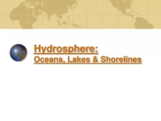
Deep water cooling Courtesy Cornell University www.utilities.cornell.edu/LSC
Annual average Coefficient of Performance (COP) • Electric centrifugal chillers including auxilliaries 4-5 • Deep water cooling • Direct free cooling 50-70 • Including seasonal storage 40-50
Södertälje, Sweden • Telgi Energi uses cold water from Lake Mälaren provides cooling to a large pharmaceutical plant and other commercial customers • Production capacity 17,000 tons • Supply temperature less than 48F all year long • Source depth 148 ft • Supply flow rate 26,400 gpm • District cooling distribution 3.7 miles of 39 inch diameter polyethylene pipe
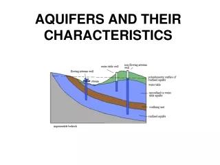
Sollentuna, Sweden • Operated by Sollentuna Energi • Production capacity 1,100 tons • Aquifer storage capacity 730,000 ton-hrs • Supply temperature 45F • Source depth 50 feet • Pipe materials • Polyethylene for pipe installed in the bay • Stainless steel for customer connections • Carbon steel for underground pipe
Integration of deep water cooling and seasonal aquifer storage
Role of seasonal storage in Sollentuna annual cooling production
Södertälje Environmental Report • Environmental impact report • Prepared by Anders Broberg, Ph.D., Swedish Institute of Limnology • Translated from Swedish by Gordon Bloomquist • Major issues • Laying of pipeline (approximately 6 km or 3.5 miles) • Turbidity • Mercury • Intake of water • Discharge of water at elevated temperature • Heating of water surrounding pipe line • Nutrients
Cooling outfall Courtesy Cornell University www.utilities.edu/LSC
Thanks for your attention!Questions? Mark Spurr Vice President FVB Energy Inc. 150 South 5th Street Minneapolis, MN 55402 Phone: 612/607-4544 Fax: 612/338-3427 mspurr@fvbenergy.com www.fvbenergy.com