Download
1 / 24
260 likes | 639 Views
Chapter 8 Multiplexing. Frequency-Division Multiplexing Synchronous Time-Division Multiplexing Statistical Time-Division Multiplexing Asymmetric Digital Subscriber Line. (a). (b). A. A. A. A. Trunk group. B. B. B. MUX. DMUX. B. C. C. C. C. Multiplexing.

E N D
Chapter 8 Multiplexing • Frequency-Division Multiplexing • Synchronous Time-Division Multiplexing • Statistical Time-Division Multiplexing • Asymmetric Digital Subscriber Line
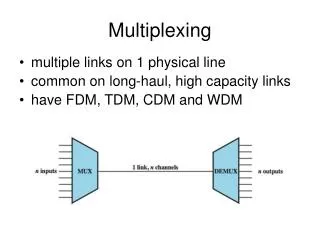
(a) (b) A A A A Trunk group B B B MUX DMUX B C C C C Multiplexing The higher the data rate, the more cost-effective the trans. facility
Frequency Division Multiplexing • A number of signals are carried simultaneously on the same medium. • Each signal is modulated to a different carrier frequency • Useful bandwidth of medium should exceed required bandwidth of channels • Carrier frequencies separated so signals do not overlap (guard bands) • e.g. FM radio, CATV • Channel allocated even if no data
A f W 0 B f 0 W C B A f C f 0 W Frequency Division Multiplexing • Individual signals occupy W Hz • The transmission channel bandwidth is divided into a number of frequency slots, each of which can accommodate the signal of an individual connection; Multiplexer assigns a frequency slot to each connections and uses modulation to place the signal of the connection in the appropriate slot
FDM System Transmitter: 1st Modulate -> Multiplex -> 2nd Modulate Receiver: 1st Demodulate->Demultiplex ->2nd Demodulate
FDM (Con’t) • AT&T analog carrier system used a hierarchy of FDM schemes • Group -12 voice channels (4kHz each) = 48kHz -Range 60kHz to 108kHz • Supergroup - 60 channel - FDM of 5 group signals on carriers between 312kHz and 552kHz • Mastergroup -10 supergroups : 2.52MHZ bandwidth between 564KHz and 3084 kHz
Synchronous Time Division Multiplexing • Data rate of medium exceeds data rate of digital signals to be transmitted • Multiple digital signals interleaved in time • Interleaving can be at: bit level; blocks of bytes level; or larger quantities level • Time slots preassignedto sources and fixed • Time slots allocated even if no data • Time slots do not have to be evenly distributed amongst sources -> TDM can handle source with different data rate.
Time Division Multiplexing TDM FDM • With FDM, each channel continuously gets a fraction of the bandwidth. • With TDM, each channel gets all of the bandwidth periodically during brief • intervals of time.
Transmitter: Buffer->Multiplex ->Modulate Receiver: Demodulate-> Demultiplex -> Buffer TDM System
Synchronous TDM Link Control • No headers and tailers for the TDM frame needed • Data link control protocols are not needed for the overall TDM link, why? • Flow control • Data rate of multiplexed line is fixed • If one channel receiver can not receive data, the others must carry on. This leaves empty slots • Data link control protocol can be used on a per-channel basis • Error control • Errors are detected and handled by individual channel systems
Framing • No flag or SYNC characters bracketing TDM frames • Must provide frame synchronization mechanism • Added digit framing • One control bit added to each TDM frame • Looks like another channel - “control channel” • Identifiable bit pattern used on control channel: e.g. alternating 01010101…unlikely on a data channel • To synchronize, a receiver compares incoming bits of one frame position to the expected sync pattern
Pulse Stuffing • Problem - Synchronizing various data sources • Clocks in different sources drifting • Data rates from different sources not related by simple rational number • Solution - Pulse Stuffing • Outgoing data rate (excluding framing bits) higher than sum of incoming rates • Stuff extra dummy bits or pulses into each incoming signal until it matches local clock • Stuffed pulses inserted at fixed locations in the multiplexer frame format, and identified/removed at demultiplexer
Digital Carrier Systems: T-1 Carrier • Digital Hierarchy of TDM • USA/Canada/Japan use this TDM structure of various capacities • ITU-T use a similar (but different) system • US system based on DS-1 format • Multiplexes 24 channels • Each frame has 8 bits per channel plus one framing bit • 193 bits per frame
1 1 2 MUX MUX 2 . . . . . . 22 23 24 1 b 24 2 b . . . frame 24 24 T-1 Carrier System • A digital Telephone speech signal is obtained by sampling a speech waveform 8000 times/sec and by representing each sample with 8 bits. • T-1 system uses a transmission frame that consists of 24slots of 8 bits each. Each slot carries one PCM sample for a single connection. • DS1: (1+24x8) bits/frame x 8000 frames/sec =1.544 Mbps
Primary Multiplex e.g. Digital Switch 24 chan PCM M23 Multiplex x7 M12 Multiplex x4 DS2 6.312 Mbps DS3 44.736 Mbps DS1 1.544 Mbps 1 Digital Signal 1 M13 Multiplex DS3 44.736 Mbps 28 T-1 Carrier System (Con’t) Higher-level multiplexing achievable by interleaving bits from DS-1 inputs -> DS2 (6.312 Mbps), DS3 (44.736Mbps)
SONET/SDH: An example of TDM • Synchronous Optical Network by BellCore (ANSI) • Synchronous Digital Hierarchy (ITU-T) • Signal Hierarchy • SONET: Synchronous Transport Signal level 1 (STS-1) or Optical Carrier level 1 (OC-1): 51.84Mbps • Can carry DS-3 or a group of lower rate signals (DS1 DS1C DS2) plus ITU-T rates (e.g. 2.048Mbps) • SDH: lowest rate is 155.52Mbps (STM-1) • SONET uses a frame structure with the same 8khz repetition rate as traditional TDM system • Multiple STS-1 combined into STS-N signal
90 bytes 87B B B B Section Overhead 3rows Information Payload 9 Rows Line Overhead 6rows 125 s Transport overhead SONET STS-1 Frame Format • Section overhead is used to provide framing, error monitoring, and other section-related management functions. • Line overhead is used to provide synchronization and multiplexing for the path layer, as well as protection-switching capacity • The first two bytes of the line overhead are used as a pointer that indicates the byte within the information payload where the SPE begins
DS1 Low-Speed Mapping Function DS2 STS-1 CEPT-1 51.84 Mbps DS3 Medium Speed Mapping Function STS-1 44.736 OC-n STS-n STS-3c STS-1 Mux E/O Scrambler CEPT-4 High- Speed Mapping Function STS-1 STS-1 139.264 STS-3c STS-1 STS-1 High- Speed Mapping Function ATM STS-1 150 Mbps SONET Multiplexing
Statistical TDM • In Synchronous TDM many slots are wasted • Statistical TDM allocates time slots dynamically based on demand -> Sequence of data packets from multiple users does not have fixed pattern as FDM & TDM • Data rate on output line lower than aggregate rates of input lines -> higher facility utilization; however, the need for “address” and “data length” causes big overhead • May cause problems during peak periods • Buffer inputs • Keep buffer size limited to reduce delay • Statistical TDM is the base for Packet Switching. While FDM and Synchronous TDM belong to Circuit Switching
Asymmetrical Digital Subscriber Line • Explore the potential capacity of the installed twisted pair (0-1MHz) • Asymmetric Digital Subscriber Line • Greater capacity downstream than upstream • Supported by Frequency division multiplexing • Lowest 25kHz for voice: plain old telephone service (POTS) • The region above 25kHz is used for data transmission • Upstream: 64kbps to 640kbps • Downstream: 1.536Mbps to 6.144Mbps
Discrete Multitone (DMT) • ITU-T G.992.1 standard for ADSL uses DMT • DMT divides available bandwidth into # of subchannels • 4kHz for each subchannels • The binary bits are distributed among the subchannel, each of which use QAM (using two copies of the carrier frequency, one shifted by 900) • More bits feed to subchannels with high SNR, less bits to subchannels with poor SNR • Current ADSL: 256 downstream subchannels (1.5 to 9Mbps).
xDSL • High data rate DSL (HDSL): deliver T1 data (1.544Mbps) over two twisted pair lines -> replace T1 lines – 1.544 or 2.048 Mbps • Single line DSL (SDSL): echo cancellation used • Very high data rate DSL: 13 to 52 Mbps downstream