Download
1 / 9
140 likes | 409 Views
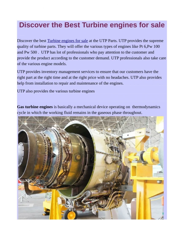
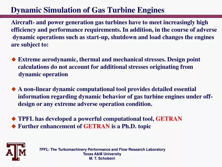
Dynamic Simulation of Gas Turbine Engines. Aircraft- and power generation gas turbines have to meet increasingly high efficiency and performance requirements. In addition, in the course of adverse dynamic operations such as start-up, shutdown and load changes the engines are subject to:

E N D
Dynamic Simulation of Gas Turbine Engines Aircraft- and power generation gas turbines have to meet increasingly high efficiency and performance requirements. In addition, in the course of adverse dynamic operations such as start-up, shutdown and load changes the engines are subject to: • Extreme aerodynamic, thermal and mechanical stresses. Design point calculations do not account for additional stresses originating from dynamic operation • A non-linear dynamic computational tool provides detailed essential information regarding dynamic behavior of gas turbine engines under off-design or any extreme adverse operation condition. • TPFL has developed a powerful computational tool, GETRAN • Further enhancement of GETRAN is a Ph.D. topic TPFL: The Turbomachinery Performance and Flow Research Laboratory Texas A&M University M. T. Schobeiri
Gas Turbine Engines, Generic Components, Modeling Twin-Spool Aircraft Gas Turbine Engine High Efficiency Power Generation Gas Turbine Engine with Sequential Combustion TPFL: The Turbomachinery Performance and Flow Research Laboratory Texas A&M University M. T. Schobeiri
Components Common to All Gas Turbine Engines Gas turbine components of different geometric configurations fulfill the same function and are described by the same set of conservation equations. This common characteristic is utilized for code development and architecture of GETRAN, which is • A GEneric modularly structured computer program for Simulating the TRANsient behavior aircraft and power generation gas turbine engines TPFL: The Turbomachinery Performance and Flow Research Laboratory Texas A&M University M. T. Schobeiri
Gas Turbine Components, Generic Modules Example of Components and module representation in GETRAN: • Uncooled and cooled turbine stage, compressor, combustion chamber For more details refer to Text: M.T. Schobeiri Turbomachinery Flow Physics And Dynamic Performance, Springer-Verlag First Edition (Second Edition in Press) TPFL: The Turbomachinery Performance and Flow Research Laboratory Texas A&M University M. T. Schobeiri
Non-linear Dynamic Engine Simulation Steps • Step 1: Expedite the engine hardware components: • No. of spools • No. of shafts, May be different from the no. of spools • No. of compressors stages on each spool • No. of turbine stages on each spool • No. of combustors • No. of diffusers, nozzles, recuperators, controllers etc. • Step 2: Generate the schematics of the engine that includes all modules with addressing. • Step 3: Provide a detailed input file that accounts for the geometry of the entire engine and some components characteristics at design point. • Step 3: Based on the geometry given, above GETRAN calculates the behavior at the design and any adverse off-design operation prescribed by the user. • An example shows, how the simulation works. TPFL: The Turbomachinery Performance and Flow Research Laboratory Texas A&M University M. T. Schobeiri
Non-linear Dynamic Engine Simulation Steps Example: Simplified engine decomposition showing major components TPFL: The Turbomachinery Performance and Flow Research Laboratory Texas A&M University M. T. Schobeiri
Non-linear Dynamic Engine Simulation Steps Example: Simplified engine decomposition showing major components Simulation of a twin-spool Core engine Note: GETRAN requires the Design point data to simulate any type of adverse off-design Operation conditions TPFL: The Turbomachinery Performance and Flow Research Laboratory Texas A&M University M. T. Schobeiri
Modeling Technology: Example Combustion Chamber Each component is modeled by a set of partial differential equations For the above combustion model, we have system of 7 PDEs: 3 PDE on the air (cold side blue), 3 PDE on hot (gad side red), 1 PDE the metal side A complete gas turbine engine has several system of PDEs. The type of adverse operation condition determine the boundary conditions TPFL: The Turbomachinery Performance and Flow Research Laboratory Texas A&M University M. T. Schobeiri
One Example of an Adverse Operation For forcing a gas turbine with split shaft into rotating stall and surge Note: the high frequency surge with intermittently positive and negative mass flow GETRAN, row-by-row compressor and turbine component calculation. TPFL: The Turbomachinery Performance and Flow Research Laboratory Texas A&M University M. T. Schobeiri