Download

1 / 36
380 likes | 630 Views
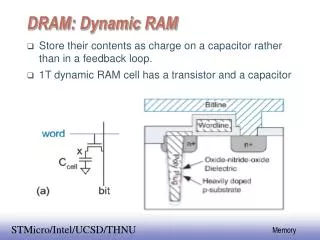
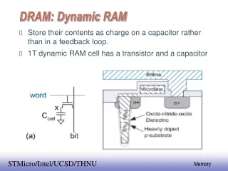
DRAM Packages. Physical DRAM Packages. Physically, the main memory in a system is a collection of Chips or Modules containing chips that are usually plugged into the motherboard.

E N D
Physical DRAM Packages • Physically, the main memory in a system is a collection of • Chips or • Modules containing chips • that are usually plugged into the motherboard. • These chips or modules vary in their electrical and physical designs and must be compatible with the system into which they are being installed to function properly.
CPU and Chipset • The CPU and motherboard architecture (chipset) dictates a particular computer’s physical memory • Capacity, • Speed and • Data bus width requirements • that can be installed.
Individual Memory Chips • Originally, systems had memory installed via individual chips. • They are often referred to as dual inline package (DIP)chips because of their designs. • The original IBM XT and AT had 36 sockets on the motherboard • for these individual chips, and then more of them were installed on the memory cards plugged into the bus slots.
Problems of using DIPMemory Chips • Time-consuming, and Labor-intensive way to deal with memory, • They crept out of their sockets over time.
Solution • The alternative to this at the time was to have the memory soldered into either the motherboard or an expansion card. • Made memory troubleshooting difficult.
Module • What was necessary was a chip that was both soldered and removable, and that is exactly what was found in the module called a SIMM.
Different types of Module • For memory storage, most modern systems have adopted the • SIMM (single inline memory module), • DIMM (dual inline memory module), or • RIMM (Rambus Inline Memory Module) • as an alternative to individual memory chips.
Modules • These small boards plug into special connectors on a motherboard or memory card. • The individual memory chips are soldered to the module, so removing and replacing them is impossible. • Instead, you must replace the entire module if any part of it fails. • The module is treated as though it were one large memory chip.
SIMM (Single In-line Memory Module) • 30-pin SIMM has 8-bit data bus • 72-pin SIMM has 32-bit data bus • May have several chips (ex: 2, 3, 8, 9)
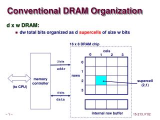
Bank of Memory • A bank of memory must contain the same amount of bits as the data bus of the CPU/System.
A typical 30-pin SIMM Dimensions The one shown here is 9-bit, although the dimensions would be the same for 8-bit.
30-pin and 72-pin SIMM Pictures http://www.simmtester.com/page/news/showpubnews.asp?num=44
Characteristics of 168-pin SDRAM DIMM • The DIMM uses serial presence detect (SPD). • It consists of a small EEPROM or Flash memory chip on the DIMM that contains specially formatted data indicating the DIMM’s features. • This serial data enables the motherboard to autoconfigure to the exact type of DIMM installed.
Characteristics of 168-pin SDRAM DIMM • DIMMs can come in several varieties, including • unbuffered or buffered and • 3.3V or 5V. • All PC systems use unbuffered DIMMs. • DIMM designs for PCs are almost universally 3.3V. • If you install a 5V DIMM in a 3.3V socket, it would be damaged, but fortunately, keying in the socket and on the DIMM prevents that.
Installing SIMM • Align the module (notch and protrusions in the socket). The notch on this SIMM is shown on the left side. • Insert the SIMM at a 45° angle • and then tilt it forward until the locking clips snap into place.
Removing SIMM • Pull plastic tabs outward • Push the top at an angle away from the socket • Pull out of the socket
Installing DIMM / RIMM • Align the module (notch and protrusions in the socket) • Insert at a straight angle (90º) • Push until the ejector tab locks into place in the notch on the side of the DIMM.
Removing DIMM / RIMM • Push out the ejector tabs and the DIMM will pop out.
72-pin SODIMM (Small Outline DIMMs) 72-pin SODIMMs are typically used in the Pentium-II Laptop computer system
144-pin SODIMM (Small Outline DIMMs) • 144- SODIMMs are typically used in the PC66 and PC100 SDRAM Laptop compatible computers
100-pin SODIMM (Small Outline DIMMs) • 100- PIN DIMMs are primarily used in printers
144- PIN Micro-DIMMs • 144- PIN Micro-DIMMs are primarily used in digital assistants, subnotebooks and notebook computers.