Download
1 / 65
670 likes | 816 Views
Exploiting Locality in DRAM. Xiaodong Zhang Ohio State University Collaborations with Zhao Zhang (Iowa State University) Zhichun Zhu (University of Illinois at Chicago). Where is Locality in DRAM?. DRAM is the center of memory hierarchy: High density and high capacity

E N D
Exploiting Locality in DRAM Xiaodong Zhang Ohio State University Collaborations with Zhao Zhang (Iowa State University) Zhichun Zhu (University of Illinois at Chicago)
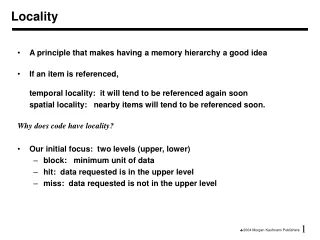
Where is Locality in DRAM? • DRAM is the center of memory hierarchy: • High density and high capacity • Low cost but slow access (compared to SRAM) • A cache miss has been considered as a constant delay for long time. This is wrong. • Non-uniform access latencies exist within DRAM • Row-buffer serves as a fast cache in DRAM • Its access patterns here have been paid little attention. • Reusing buffer data minimizes the DRAM latency. • Larger buffers in DRAM for more locality.
Outline • Exploiting locality in Row Buffers • Analysis of access patterns. • A solution to eliminate conflict misses. • Cached DRAM (CDRAM) • Design and its performance evaluation. • Large off-chip cache design by CDAM • Major problems of L3 caches. • Address the problems by CDRAM. • Memory access scheduling • A case for fine grain scheduling.
Locality Exploitation in Row Buffer CPU registers Registers TLB TLB L1 L1 L2 L2 L3 L3 CPU-memory bus Row buffer Row buffer Bus adapter DRAM Controller buffer Controller buffer Buffer cache Buffer cache I/O bus I/O controller disk cache Disk cache disk
Exploiting the Locality in Row Buffers • Zhang, et. al., Micro-33, 2000, (W&M, now at Ohio State) • Contributions of this work: • looked into the access patterns in row buffers. • found the reason behind misses in the row buffer. • proposed an effective solution to minimize the misses. • The result in this paper has beenadoptedin Sun UltralSPARC IIIi Processors and other types of processors, operating on millions of workstations, servers, and, embedded CPUs.
Row Access Precharge DRAM Access=Latency+ Bandwidth Time Processor Bus bandwidth time Row Buffer Column Access DRAM Latency DRAM Core Row buffer misses come from a sequence of accesses to different pages in the same bank.
Nonuniform DRAM Access Latency • Case 1: Row buffer hit (20+ ns) • Case 2: Row buffer miss (core is precharged, 40+ ns) • Case 3: Row buffer miss (not precharged, ≈ 70 ns) col. access row access col. access precharge row access col. access
Amdahl’s Law applies in DRAM • Time (ns) to fetch a 128-byte cache block: latencybandwidth • As the bandwidth improves, DRAM latency will decide cache miss penalty.
Row Buffer Locality Benefit Objective: serve memory requests without accessing the DRAM core as much as possible. Reduce latency by up to 67%.
Row Buffer Misses are Surprisingly High • Standard configuration • Conventional cache mapping • Page interleaving for DRAM memories • 32 DRAM banks, 2KB page size • SPEC95 and SPEC2000 • What is the reason behind this?
Conventional Page Interleaving Page 0 Page 1 Page 2 Page 3 Page 4 Page 5 Page 6 Page 7 … … … … Bank 0 Bank 1 Bank 2 Bank 3 Address format r k p page index bank page offset
Conflict Sharing in Cache/DRAM • cache-conflicting: same cache index, different tags. • row-buffer conflicting: same bank index, different pages. • address mapping: bank index cache set index • Property: xy, x and y conflict on cache also on row buffer. r k p page: page index bank page offset t s b cache: cache tag cache set index block offset
Sources of Misses • Symmetry: invariance in results under transformations. • Address mapping symmetry propogates conflicts from cache address to memory address space: • Cache-conflicting addresses are also row-buffer conflicting addresses • Cache write-back addressconflicts with the address of the to be fetched block in the row-buffer. (write-back page replaces the fetched page, which will be re-fetched to row buffer before loading to cache) • Cache conflict misses are also row-buffer conflict misses.
L2 Cache tag index bank page offset k k XOR k page index new bank page offset Breaking the Symmetry by Permutation-based Page Interleaving
Permutation-based interleaving Conventional interleaving memory banks L2 Conflicting addresses 0000 1000 1010 0001 0010 0011 1001 1010 0100 0101 1010 1010 0110 0111 1010 1011 1010 1011 xor Different bank indexes Same bank index Permutation Property (1) • Conflicting addresses are distributed onto different banks
Permutation-based interleaving Conventional interleaving memory banks Within one page 0000 1000 1010 0001 1000 1010 0010 1000 1010 0011 0100 1000 1010 0101 … … 0110 0111 1010 1011 xor Same bank index Same bank index Permutation Property (2) • The spatial locality of memory references is preserved.
bank 0 bank 1 bank 2 bank 3 Permutation Property (3) • Pages are uniformly mapped onto ALL memory banks. 0 1P 2P 3P 4P 5P 6P 7P … … … … C+1P C C+3P C+2P C+5P C+4P C+7P C+6P … … … … 2C+2P 2C+3P 2C 2C+1P 2C+6P 2C+7P 2C+4P 2C+5P … … … …
Where to Break the Symmetry? • Break the symmetry at the bottom level (DRAM address) is most effective: • Far away from the critical path (little overhead) • Reduce the both address conflicts and write-back conflicts. • Our experiments confirm this (30% difference).
Impact to Commercial Systems • Critically show the address mapping problem in Compaq XP1000 series with an effective solution. • Our method has been adopted in Sun UltraSPARC IIIi processor: XOR interleaving, or permutation interleaving • Chief architect Kevin Normoyle had intensive discussions with us for this adoption in 2001. • The results in the Micro-33 paper on ``conflict propagation”, and ``write-back conflicts” are quoted in the Sun Ultra SPARC Technical Manuals. • Sun Microsystems has formally acknowledged our research contribution to their products. • It is also used in Sun’s Gemini dual-core processor.
What roles does UltraSPARC IIIi Play? • UltraSPARC IIIi is a flagship processor in Sun products. • Up to 1.593 GHz • L2 cache: 1 MB on-chip, 4-way associative • Multiprocessor: up to 4 processors • In a wide range of Sun computer products: • Sun Fire servers (V210, V240, V250, and V440 Servers) • Workstations and Desktops: Sun Blade 1500 series.
Other Impacts • Several other processor chips use the xor permutation: • AMD Geode, Geode LX, and GX3 processors • Mobile Intel 4 Series Express Chipset Family • NVIDIA Chipset (GeForce 7025/Nforce 630a) • In Architecture Textbooks • Memory Systems: Cache, DRAM, Disks, B. Jacob, et. al. (2005) • Microprocessor Architecture, J-L. Baer (2009) • Supporting multiple DRAM patents • Programmable DRAM (HP) • Low power DRAM (Freescale Semiconductor Inc.)
Acknowledgement from Sun MicroSystems • Sun Microsystems, Inc. has applied the permutation-based memory interleaving technique, called ``XOR interleaving" or ``permutation interleaving" as proposed by Zhao Zhang (Ph.D.'02), Zhichun Zhu (Ph.D.'03), and Xiaodong Zhang (Lettie Pate Evans Professor of Computer Science and the Department Chair) at the College of William and Mary, in the Sun UltraSPARC IIIi processors. • A paper about this technique entitled "A permutation-based page interleaving scheme to reduce row-buffer conflicts and exploit data locality" was published in the 33rd Annual IEEE/ACM International Symposium on Microarchitecture (Micro-33, pp. 32-41, Monterey, California, December 10-13, 2000). A chief finding demonstrated in the report by the three researchers was that address mapping conflicts at the cache level, including address conflicts and write-back conflicts, may inevitably propagate to DRAM memory under a standard memory interleaving method, causing significant memory access delays. The proposed permutation interleaving technique proposed a low cost solution to these conflict problems. Marc Tremblay, Sun Fellow, Vice President & Chief Architect
Outline • Exploiting locality in Row Buffers • Analysis of access patterns. • A solution to eliminate conflict misses. • Cached DRAM (CDRAM) • Design and its performance evaluation. • Large off-chip cache design by CDAM • Major problems of L3 caches. • Address the problems by CDRAM. • Memory access scheduling • A case for fine grain scheduling.
Can We Exploit More Locality in DRAM? • Cached DRAM: adding a small on-memory cache in the memory core. • Exploiting the locality in main memory by the cache. • High bandwidth between the cache and memory core. • Fast response to single memory request hit in the cache. • Pipelining multiple memory requests starting from the memory controller via the memory bus, the cache, and the DRAM core (if on-memory cache misses happen).
CPU Low bandwidth in cache line per bus cycle L1 Cache Memory Bus High bandwidth in page per internal bus cycle Cached DRAM L2 Cache On Memory Cache DRAM Core Cached DRAM
Cached DRAM vs. XOR Interleaving(16 × 4 KB on-memory cache for CDRAM,32 × 2 KB row buffers for XOR interleaving among 32 banks)
Cons and Pros of CDRAM over xor Interleaving • Merits: • High hits in on-memory cache due to high associativity. • The cache can be accessed simultaneously with DRAM. • More cache blocks than the number of memory banks. • Limits: • Requires an additional chip area in DRAM core and additional management circuits.
Outline • Exploiting locality in Row Buffers • Analysis of access patterns. • A solution to eliminate conflict misses. • Cached DRAM (CDRAM) • Design and its performance evaluation. • Large off-chip cache design by CDAM • Major problems of L3 caches. • Address the problems by CDRAM. • Memory access scheduling • A case for fine grain scheduling.
Large Off-chip Caches by CDRAM • Large and off-chip L3 caches are commonly used to reduce memory latency. • It has some limits for large memory intensive applications: • The size is still limited (less than 10 MB). • Access latency is large (10+ times over on-chip cache) • Large volume of L3 tags (tag checking time prop log (tag size) • Tags are stored off-chip. • Study shows that L3 can degrade performance for some applications (DEC Report 1996).
Can CDRAM Address L3 Problems? • What happens if L3 is replaced CDRAM? • The size of CDRAM is sufficiently large, however, • How could its average latency is comparable or even lower than L3 cache? • The challenge is to reduce the access latency to this huge ``off-chip cache” . • ``Cached DRAM Cache” (CDC) addresses the L3 problem, by Zhang et. al. published in IEEE Transactions on Computers in 2004.(Ohio State)
Cached DRAM Cache as L3 in Memory Hierarchy L1 Inst Cache L1 Data Cache CDC tag cache and predictor L2 Unified Cache Memory bus CDC-cache CDC-DRAM DRAM main memory
How is the Access Latency Reduced? • The tags of the CDC cache are stored on-chip. • Demanding a very small storage. • High hits in CDC cache due to high locality of L2 miss streams . • Unlike L3, the CDC is not between L2 and DRAM. • It is in parallel with the DRAM memory. • An L2 miss can either go to CDC or DRAM via different buses. • Data fetching in CDC and DRAM can be done independently. • A predictor is built on-chip using a global history register. • Determine if a CDC miss will be a hit/miss in CDC-DRAN. • The accuracy is quite high (95%+).
Modeling the Performance Benefits L3 Cache System: Average memory access time = Hit_Time (L1) + Miss_Rate (L1) × Miss_Penalty (L1), where Miss_Penalty (L1) = Hit_Time (L2) + Miss_Rate (L2) × Miss_Penalty (L2), where Miss_Penalty (L2) = Hit_Time (L3) + Miss_Rate (L3) × Memory_Access_Time. CDC System: Average memory access time = Hit_Time (L1) + Miss_Rate (L1) × Miss_Penalty (L1), where Miss_Penalty (L1) = Hit_Time (L2) + Miss_Rate (L2) × Miss_Penalty (L2), where Miss_Penalty (L2) = Hit_Time (CDC_Cache) + Miss_Rate (CDC_Cache) × Miss_Penalty (CDC_Cache) Miss_Penalty(L2) for each system is the determining performance factor.
A CDC_Cache miss requests the predictor to determine where to search the missed data: CDC-DRAM or the main memory? Three possibilities of Miss_Penalty (CDC_Cache): prediction is correct, and hit in CDC_DRAM: CDC_DRAM access time; prediction is correct, and hit in main memory: memory access time; prediction is wrong. and data miss in CDC_DRAM: CDC_DRAM access time + memory access time. Note: P is the prediction accuracy in %. Miss_Penalty (CDC_Cache) = CDC_DRAM_Access_Time × (1 - Miss_Rate (CDC_DRAM)) × P + Memory_Access_Time × (1 - Miss_Rate (CDC_DRAM)) × (1-P) + Memory_Access_Time × Miss_Rate (CDC_DRAM) × P + (CDC_DRAM_Access_Time + Memory_Access_Time) × Miss_Rate (CDC_DRAM) × (1-P) Miss_Penalty (CDC_Cache)
Parameters of the Two Systems (Zhang et. al., TC, 04) • Hardware Parameters Memory_Access_Time = 2.5 × CDC_DRAM_Access_Time = 100 cycles Hit_Time (L3) = 1.2 × Hit_Time (CDC_Cache) = 24 cycles. • Workload Parameters (for 64MB CDC, 8 MB L3)Hit_Rate (CDC_Cache) = 58.6% Hit_Rate (CDC_DRAM) = 76.2% Prediction Accuracy = 96.4% Hit_Rate(L3) = 42%. • L3 System: Miss_Penalty(L2) = 1.2 × Hit_Time (CDC_Cache) + 58% × Memory_Access_Time
Comparing Miss_Penalty (L2) between L3 and CDC Systems • In CDC System: Miss_Penalty (L2) = Hit_Time (CDC_Cache) + (1 – 58.6%) × (1/2.5 × Memory_Access_Time × 76.2% × 96.4% + Memory_Access_Time × 76.2% × 3.6% + Memory_Access_Time × 23.8% × 96.4% + (1/2.5 × Memory_Access_Time + Memory_Access_Time) × 23.8% × 3.6%) = Hit_Time (CDC_Cache) + 41.4% × (0.294 × Memory_Access_Time + 0.027 × Memory_Access_Time + 0.229 × Memory_Access_Time + 0.012 × Memory_Access_Time) = Hit_Time (CDC_Cache) + 0.233 × Memory_Access_Time • Miss_Penalty(L2) of L3 / Miss_Penalty(L2) of CDC = 1.89 • 89% more latency in L2 miss in the L3 system than that in the CDC system.
Advantages and Performance Gains • Unique advantages • Large capacity, equivalent to the DRAM size, and • Low average latency by (1)exploiting locality in CDC-cache, (2)fast on-chip tag checking for CDC-cache data, (3)accurate prediction of hit/miss in CDC-DRAM, and (4) high bandwidth data transfer from CDC-DRAM. • Performance of SPEC2000 • Outperforms L3 organization by up to 51%. • Unlike L3, CDC does not degrade performance of any. • The average performance improvement is 25%.
Outline • Exploiting locality in Row Buffers • Analysis of access patterns. • A solution to eliminate conflict misses. • Cached DRAM (CDRAM) • Design and its performance evaluation. • Large off-chip cache design by CDAM • Major problems of L3 caches. • Address the problems by CDRAM. • Memory access scheduling • A case for fine grain scheduling.
Memory Access Scheduling • Objectives: • Fully utilize the memory resources, such as buses and concurrency of operations in banks and transfers. • Minimizing the access time by eliminating potential access contention. • Access orders based on priorities make a significant performance difference. • Improving functionalities in Memory Controller.
Memory Controller Memory Scheduling Unit FIFO MainMemory FIFO CPU FIFO Address Mapping Unit Stream Buffer Unit Memory accesses issued in the requested order Cache Memory accesses issued in an “optimal” order
Basic Functions of Memory Controller • Where is it? • A hardware logic directly connected to CPU, which generates necessary signals to control the read/write, and address mapping in the memory, and interface other memory with other system components (CPU, cache). • What does it do specifically? • Pipelining and buffering the requests • Memory address mapping (e.g. XOR interleaving) • Reorder the memory accesses to improve performance.
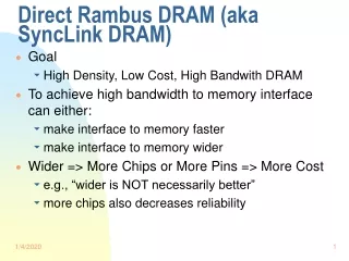
Complex Configuration of Memory Systems • Multi-channel memory systems (e.g. Rambus) • Each channel connects multiple memory devises. • Each devise consists multiple memory banks. • Concurrent operations among channels and banks. • How to utilize rich multi-channel resources? • Maximizing the concurrent operations. • Deliver a cache line with critical sub-block first.
… …… … Channel C-1 …… Channel 0 Bank 0 Bank B-1 … …… … Device 0 Device D-1 Multi-channel Memory Systems CPU /L1 L2
multiple DRAM Requests (in the same bank) Partitioning A Cache Line into sub-blocks • Smaller sub-block size shorter latency for critical sub-blocks • DRAM system: minimal request length • Sub-block size = smallest granularity available for Direct Rambus system a cache miss request