Download
1 / 52
520 likes | 603 Views
Changes to the PS RF system. H. Damerau Many thanks for discussions and input to L. Arnaudon , D. Cotte , S. Hancock, R. Maillet , M. Morvillo, M. Paoluzzi , D. Perrelet, S . Rains, C. Rossi, S. Totos. 55. BE/OP Shutdown Courses 2014. 04 April 2014. Overview. Introduction

E N D
Changes to the PS RF system H. Damerau Many thanks for discussions and input to L. Arnaudon, D. Cotte, S. Hancock, R. Maillet, M. Morvillo, M. Paoluzzi, D. Perrelet, S. Rains, C. Rossi, S. Totos 55 BE/OP Shutdown Courses 2014 04 April 2014
Overview • Introduction • RF systems for manipulations • Global beam control system modifications • Injection bucket control • RF controls renovation • 10 MHz RF system • Voltage control and 1-turn delay feedback loops • Tuning group restructuring • 10 MHz matrix control, spare cavity selection and linked timing • High-frequency and wide-band RF systems • 20, 40, 80 MHz and 200 MHz • Wideband cavity for longitudinal damper • Summary
Overview • Introduction • RF systems for manipulations • Global beam control system modifications • Injection bucket control • RF controls renovation • 10 MHz RF system • Voltage control and 1-turn delay feedback loops • Tuning group restructuring • 10 MHz matrix control, spare cavity selection and linked timing • High-frequency and wide-band RF systems • 20, 40, 80 MHz and 200 MHz • Wideband cavity for longitudinal damper • Summary
Introduction PS Protons to fixed target experiments Protons from PSB • Protons and ions to SPS (and LHC) • Protons to AD and nTOFtarget Pb54+ (future: Ar11+, Xe39+) from LEIR • Beams from single bunch to 72 bunches, flexible longitudinal pattern • Intensity range from about 109 to 3 · 1013 particles per cycle • Major bunch shortening along the cycle, from 180 ns to 4 ns (45 times!) • After LS1: BCS, BCMS, PBC, etc. • What has changed for the RF systems after LS1? • What to do with the modified RF systems? Steven’s lecture
RF Systems to perform manipulations RF Manipulations 2.8 – 10 MHz 40 MHz Acceleration to SPS PS 80 MHz 200 MHz Longitudinal blow-up and 200 MHz structure for SPS 13/20 MHz RF Manipulations 24 (+1) cavities from 2.8 to 200 MHz
Overview • Introduction • RF systems for manipulations • Global beam control system modifications • Injection bucket control • RF controls renovation • 10 MHz RF system • Voltage control and 1-turn delay feedback loops • Tuning group restructuring • 10 MHz matrix control, spare cavity selection and linked timing • High-frequency and wide-band RF systems • 20, 40, 80 MHz and 200 MHz • Wideband cavity for longitudinal damper • Summary
Injection bucket selection PA.DCNBINJ • Bunches from PSB must be placed into the correct buckets • Batch compression works only for even number of bunches 1 turn • Bucket number control during both transfers PSB PS
Synchronizing PSB and PS – 1st injection Tagged clock DDS h128 MHS DDS R. Garoby, Multi-harmonic RF Source for the Anti-proton Production Beam of AD, CERN PS/RF/Note 97-10 frev, closed loop RF directly to cavities (one DDS per cavity) … … Bucket number control • Sync. on h = 1, fix bucket # Inj. Bucket selection fRF, inj. = 9 · 436.568 MHz 2. Inj. 1. Df(phase loop) MHS h = 1 Shifted trains to PSB, 1st inj. MHS hPL = 9 Df(injection synchro.) • Lock f- loop on inj. synth. 4 ms/div Generate synchronous h1, h4 and h8 for PSB, while locking f-loop on h9
Synchronizing PSB and PS – 2nd injection Tagged clock DDS h128 MHS DDS R. Garoby, Multi-harmonic RF Source for the Anti-proton Production Beam of AD, CERN PS/RF/Note 97-10 frev, closed loop RF directly to cavities (one DDS per cavity) … … Bucket number control • Sync. on h = 1, fix bucket # Inj. Bucket selection MHS h = 1 Shifted trains to PSB, 2nd inj. MHS hPL = 9 Generate synchronous h1, h4 and h8 for PSB, while locking f-loop on h9
Overview • Introduction • RF systems for manipulations • Global beam control system modifications • Injection bucket control • RF controls renovation • 10 MHz RF system • Voltage control and 1-turn delay feedback loops • Tuning group restructuring • 10 MHz matrix control, spare cavity selection and linked timing • High-frequency and wide-band RF systems • 20, 40, 80 MHz and 200 MHz • Wideband cavity for longitudinal damper • Summary
Major renovation of LLRF controls • Profit from global controls renovation (ACCOR) to move front-ends for PS beam controls to central building Before The plan…
Major renovation of LLRF controls • Profit from global controls renovation (ACCOR) to move front-ends for PS beam controls to central building During… Back on… E. Said and installation team • Close collaboration between BE/CO and BE/RF
Migration of controls devices ‘Transparent’ migration • 67 CVORB function channels • ~220 physical timing channels, ~1240 timings in total (multi-pulses) • ~35 Further devices: digital controls, RF synthesizer, etc. • Kontron PC front-end for MIL1553 loops (all cavities) on/off/reset • About 10 kilometers of new cables, but in about 250 smaller pieces
Ready for new RF manipulations • Controls upgrade from TG8 to CTRV: • Each function with restarts now 16 instead of 8 restart timings • Twice more complicated RF manipulations possible: • Sequence of 16 phase loop harmonics • Sequence of 20-25 RF harmonics • RF manipulations twice as complicated as before LS1 (2 BCMS) • Should be sufficient for the near future? • Should be sufficient for the future
Overview • Introduction • RF systems for manipulations • Global beam control system modifications • Injection bucket control • RF controls renovation • 10 MHz RF system • Voltage control and 1-turn delay feedback loops • Tuning group restructuring • 10 MHz matrix control, spare cavity selection and linked timing • High-frequency and wide-band RF systems • 20, 40, 80 MHz and 200 MHz • Wideband cavity for longitudinal damper • Summary
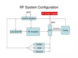
PS 10 MHz feedback overview Final Amplifier, 10 MHz Cavity, FastWideband FB Gap Return - Fast wide-band feedback around amplifier (internal) Gain limited by delay - 1-turn delay feedback High gain at n frev - Slow voltage control loop (AVC) Gain control at fRF Drive DAC 1TFB ADC DAC AVC h h200 Vprog(digital) D. Perrelet H
Voltage control (AVC) loop • Pre-LS1 hardware required analog voltage program • Regulation characteristics not optimum for fast voltage jumps P. Maesen, PS/RF/Note 94-25 RF from beam control • Analog voltage control: • AVC loop functionality • Interlocks Pre-LS1 Loop filter Vprog (analog) • Upgrade to fully digital implementation of AVC loop • Migrate interlock part to separate surveillance hardware
Digital voltage control (AVC) loop • Digital voltage control loops integrated into 1-turn delay feedback HW • Separate surveillance module to assure hardware safety RF from beam control Digital PID h (digital) Veto Vprog (digital) Non-I/Q detector D. Perrelet • Harmonic number functions PA.GSHA/B/C required for all beams M. Haase
Principle of the 1-turn delay feedback • Classical feedback limited by unavoidable delay • BUT: Impedance reduction of cavities only needed at frev harmonics D. Boussard, G. Lambert, PAC83, pp. 2239-2241 • Comb filter for high gain at frev harmonics • Delay circuit to correct total feedback delay to a full turn • Additional notch filter to cancel feedback gain at fRF
New 1-turn delay feedback • No need for: • Multiple clocks, avoiding double sampling at 4 fRF and 80 frev • Wide-range clock phase locked loops • External delay cables • Increased resolution of signal processing from 10 to 14 bits • Ready for proton beams at any harmonic number • No need to start from h = 8 (limitation in old system) • Compatible with all LHC-type beams • Integrated electronic delay generation • Possibility to raise feedback gain by firmware improvements • Include a digital AVC in the firmware to replace analog hardware
Flexible feedback board development D. Perrelet • Versatile board: • 4 ADC/DAC channels with powerful FPGA • Delay line chains to complete delay of 1-turn • CVORB and fast serial ports for connections • Further/future applications: PS transverse feedback, coupled-bunch feedback, 1-turn delay feedback for 20/40/80 MHz systems and transverse dampers of PSB, AD, LEIR
Installation • Four new VME crates installed in building 359 (one per tuning group) • Example for tuning group B (cavities C56, C66, C76 and C81): D. Perrelet All 10 MHz cavities equipped: AVC loop commissioning ongoing, then 1-turn delay feedback
Overview • Introduction • RF systems for manipulations • Global beam control system modifications • Injection bucket control • RF controls renovation • 10 MHz RF system • Voltage control and 1-turn delay feedback loops • Tuning group restructuring • 10 MHz matrix control, spare cavity selection and linked timing • High-frequency and wide-band RF systems • 20, 40, 80 MHz and 200 MHz • Wideband cavity for longitudinal damper • Summary
Change of tuning group configuration • 10 MHz require a tuning current of up to 3000 A to cover 2.8…10 MHz • Multiple cavities in series to reduce tuning power supplies: • 3+1 tuning power supplies since 1984 • Two groups of 2 cavities and one big group (2 + 2 + 6) • For RF manipulations voltage limited to 40 kV per group • Change tuning group configuration to 3 + 3 + 4 • Adapt to present needs • 60 kV per group Below PS ring (inside) • Rewire 3 kA cables!
Rewiring 3 kA cables: before Connection box below C10-56 To C51 To C66 To C51 To C66 V. Desquiens Connections to C56
Rewiring 3 kA cables: after Connection box below C10-56 To C51 To C66 To C51 To C66 V. Desquiens Connections to C56
Frequency: Fixed tuning circuits (1984-2013) Tuning-Groups: hA: 36, 46 hB: 51, 56, 66, 76, 81, 91 hC: 86, 96 Group 4: 11, test cavity → All cavities of group tuned to same frequency → Hard-wired structure of tuning groups → 40 kV in three groups
Frequency: Fixed tuning circuits (2013-) Tuning-Groups: hA: 36, 46, 51 hB: 56, 66, 76, 81 hC: 86, 91, 96 Group 4: 11, test cavity → All cavities of group tuned to same frequency → Hard-wired structure of tuning groups → 60 kV in three groups
Tuning group change: status and consequences • Behavior of tuning groups verified before and after the change • First six cavities in the ring now pulsing • But: • All cavities in voltage program group should be in same tuning group • Now violated for almost all cycles • Need to adapt timing trees ( Steven’s presentation) • Need to rebuilt each cycle before it can be executed! • Major effort of reprogramming all RF functions • Please do not just put pre-LS1 cycles in the super-cycle! Absolutely ‘non-transparent’
Overview • Introduction • RF systems for manipulations • Global beam control system modifications • Injection bucket control • RF controls renovation • 10 MHz RF system • Voltage control and 1-turn delay feedback loops • Tuning group restructuring • 10 MHz matrix control, spare cavity selection and linked timing • High-frequency and wide-band RF systems • 20, 40, 80 MHz and 200 MHz • Wideband cavity for longitudinal damper • Summary
Voltage program generation: hardware matrix • Hardware matrix has served from the mid 1990’s until LS1 • Complicated hardware with embedded micro-processor • 6 analog functions + 12 timings in 11 analog function + 22 timings out Pre-LS1 Functions and timings per group Functions and timings per cavity • Few spare boards in unknown state left • Dangerous single point of failure
Voltage program generation Global program Mapping from groups to cavities • voltage programs • gap relay timings 0…200 kV Global red. × 0…100% Modifier grp. 1 × Modifier grp. 2 × Modifier grp. 3 × Modifier grp. 4 × Modifier grp. 5 × Modifier grp. 6 × 0…100% Voltage programs to cavities: C11 C36 C46 C51 C56 C66 C76 C81 C86 C91 C96
New software based 10 MHz matrix • New implementation guidelines: • Distribution of digital voltage program data to each cavity • CVORB function generator channel and CTRV timings per cavity • No specific central hardware as single point of failure • Only simple electronics to distribute serial data streams • Move relevant parts of matrix to software virtual matrix • Combine functions and restart timings to so-called real-time function per voltage program group • Copy real time functions per group to functions per cavity • Major implementation effort by P. Pera Mira and G. Kruk H. D., S. Hancock, CERN-ATS-Note-2013-021 TECH
Real-time function generation • Voltage program modifier functions per group (with restarts) difficult to map • Calculate real-time functions PA.GS…RT, based on functions and timings • Copy only real-time (RT) functions to the functions per cavity Function with restarts Real-time function ( ) • Functions per group drive no hardware anymore • Possibility to virtualize later
Voltage program generation Global program Mapping from groups to cavities • voltage programs • gap relay timings 0…200 kV Global red. × 0…100% Modifier grp. 1 × Modifier grp. 2 × • Hardware switching of functions and timings migrated to software • InCAMakeRules to copy settings from groups to cavities • Integrated spare cavity selection mechanism for C11 • Virtual matrix Modifier grp. 3 × Modifier grp. 4 × Modifier grp. 5 × Modifier grp. 6 × Modifier grp. 7 × Modifier grp. 8 × 0…100% Voltage programs to cavities: C11 C36 C46 C51 C56 C66 C76 C81 C86 C91 C96
Upgraded distribution of voltage programs • More flexibility thanks to renovated generation of voltage programs: so-called ‘matrix’ • New hardware to generate digital voltage program data for each cavity • 8 logical groups of cavities • Matrix functionality implemented in software • Commissioned and essentially ready for start-up
Application program • New application (D. Cotte, R. Maillet) • Finally little changes from the operations point of view • Integrated spare cavity selection, also based on InCAMakeRules
Spare cavity selection • Spare cavity C11 replaces any other 10 MHz cavity, needs: • Voltage program like any other cavity • Harmonic number and relative phase special • Previous implementation: hardware multiplexers for GFAS functions • MakeRules now copy relevant functions and timings on all LSA cycles Tuning group of cavity to be replaced by C11 PA.GSHART PA.GSRPART PA.GSHDRT PA.GSRPDRT PA.GSHBRT PA.GSRPBRT A, B or C A, B or C PA.GSHCRT PA.GSRPCRT Harmonic Relative phase • No dedicated hardware involved anymore • Flexible, could even drive C11 with its own functions and timings
Overview • Introduction • RF systems for manipulations • Global beam control system modifications • Injection bucket control • RF controls renovation • 10 MHz RF system • Voltage control and 1-turn delay feedback loops • Tuning group restructuring • 10 MHz matrix control, spare cavity selection and linked timing • High-frequency and wide-band RF systems • 20, 40, 80 MHz and 200 MHz • Wideband cavity for longitudinal damper • Summary
Glue logic for the control: linked timing Pre-LS1 … … … … • Timing tree structure assures coherence between harmonic number (tuning group)and voltage programs (matrix) • Old timing trees (LKTIM) incompatible with LTIM/CTRV timings • Migration of X-motif application to Java needed • New trees again with node and parent lists (Mbno device ID) • Rules for timing and status calculation moved to InCA `
Glue logic for the control: linked timing • New application (D. Cotte, G. Kruk for the InCA part): • Little changes from the operations point of view • Comfortable handling of large timing trees, commissioning ongoing
Overview • Introduction • RF systems for manipulations • Global beam control system modifications • Injection bucket control • RF controls renovation • 10 MHz RF system • Voltage control and 1-turn delay feedback loops • Tuning group restructuring • 10 MHz matrix control, spare cavity selection and linked timing • High-frequency and wide-band RF systems • 20, 40, 80 MHz and 200 MHz • Wideband cavity for longitudinal damper • Summary
Status of 20, 40, 80 and 200 MHz cavities • 20 MHz cavities As before LS1 • 40 MHz C40-78 repaired, being commissioned • Pre-driver amplifiers water-cooled • Otherwise as before LS1 • 80 MHz cavities Pre-driver amplifiers water-cooled • Otherwise as before LS1 • 200 MHz cavities Cavities as before LS1 • Renovation of C201/206 amplifiers All high frequency cavities will be available for the start-up
Automatic tuning for 40 and 80 MHz systems • Keep cavities at fixed frequency • Microprocessor-based system after LS1 L. Arnaudon, S. Totos • Will also pilot switching of 80 MHz cavities for protons and ions • Commissioning during/after start-up
Renovation of 200 MHz amplifiers (C201/206) New amplifiers in BA3 (SPS) • High power chain C202/C203/ C204/C205 completely renovated during the 2006/2007 shutdown • C201/206 followed during LS1 Before Old amplifiers New amplifiers S. Rains, Ch. Renaud
Renovation of 200 MHz amplifiers (C201/206) New amplifiers ready in building 151 (C201) • Amplifiers • Special old types irradicated • Interchangeable with SPS • Interlock system • More evolved then for C202-C205 • Power supplies • Reliability New amplifiers • C201/206 renovated for the start-up all systems almost identical • Strategy for operation after LS1: • Run with four 200 MHz RF systems, including C201 and C206 • Keep two cavities as hot spares
Overview • Introduction • RF systems for manipulations • Global beam control system modifications • Injection bucket control • RF controls renovation • 10 MHz RF system • Voltage control and 1-turn delay feedback loops • Tuning group restructuring • 10 MHz matrix control, spare cavity selection and linked timing • High-frequency and wide-band RF systems • 20, 40, 80 MHz and 200 MHz • Wideband cavity for longitudinal damper • Summary
New cavity (#25) in the PS ring • Wide-band (0.4 – 5.5 MHz, VRF= 5 kV) cavity based on Finemet material • No acceleration, but damping of coupled-bunch oscillations SS02 6-cell cavity unit Accelerating gap Power amplifiers(solid state) M. Paoluzzi • Cavity installed in SS02, start with amplifiers on 2 gaps • First installation of transistor power amplifiers close to beam in PS
Coupled-bunch oscillation damping • Bunches oscillate with different phases (and amplitudes) Example of an n = 12 mode (Df ≈ 206) • Mode number ndefined by phase advance from bunch-to-bunch: Df = 2pn/h Kick frf Preferred detection Kicker baseband Measure • Coupled-bunch oscillations show up as side-bands of nfrev or (h-n)frev • Frequency range of new Finemet cavity allows to damp all modes • Commissioning after start-up
Overview • Introduction • RF systems for manipulations • Global beam control system modifications • Injection bucket control • RF controls renovation • 10 MHz RF system • Voltage control and 1-turn delay feedback loops • Tuning group restructuring • 10 MHz matrix control, spare cavity selection and linked timing • High-frequency and wide-band RF systems • 20, 40, 80 MHz and 200 MHz • Wideband cavity for longitudinal damper • Summary