Download
1 / 29
300 likes | 604 Views
RF System to RF Module Interface. C Whyte, University of Strathclyde For the MICE RF team. Redesigned distribution network The demonstration experiment has simpler distribution requirements Now makes sense to use ‘over air-gap’ network Replaces STEP V under floor scheme

E N D
RF System to RF Module Interface C Whyte, University of Strathclyde For the MICE RF team MICE RF Module Engineering Review LBNL Center for Beam Physics
Redesigned distribution network • The demonstration experiment has simpler distribution requirements • Now makes sense to use ‘over air-gap’ network • Replaces STEP V under floor scheme • Muon-RF phase determination • Initial tests with waveforms from MTA tests • Hardware now at Strathclyde for RF tests • Status of RF drive system • Plans for test, delivery and installation of amplifiers • Proposal for a full system test at RAL • Requires appropriate EE and RF resources • Development of RF Controls & Monitoring systems • Development of LLRF • Resource Issues Content MICE RF Module Engineering Review LBNL Center for Beam Physics
MICE HPRF system requirements have changed • Fewer cavities, no coupling coil • Required operational date on the beamline is Summer 2017 • Requires early commissioning of the hardware: Starting Aug 2016 • Enables demonstration of ionisation cooling with re-acceleration • First results complete before end US fiscal year 2017 • The MICE Demonstration of Ionisation Cooling requires • Two cavities bracketed by two thin LiH absorbers, sandwiching main absorber MICE High Power RF systems MICE RF Module Engineering Review LBNL Center for Beam Physics
2MW peak output from RF drive amplifiers, are unchanged • LLRF ~10 % overhead to achieve regulation • Estimated <10 % loss in transmission line • Power delivered to each cavity 1.62 MW, • Anticipated gradient in each cavity 10.3 MV/m • Slight uplift in gradient from 7.2 MV/m in each ‘STEP V’ cavity MICE High Power RF systems MICE RF Module Engineering Review LBNL Center for Beam Physics
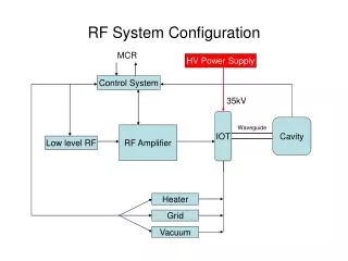
Simplified distribution network- feasible to route overhead • Off-centre mounting of hybrid takes up phase shift • Orientation of load arbitrary- align with the 6” distribution line and share mountings • Minimised length of 4” line- minimises losses 500kW Load 4616 Pre Amplifier RF network Hybrid Splitter Flexible coax Directional Coupler in each line Directional Coupler 6 inch Line Trimmers TH116 Amplifier MICE RF Module Engineering Review LBNL Center for Beam Physics
Load on each splitter to absorb unbalanced reflections • Retracted crane hook clears coax over the wall. • Support from present ‘shield wall’ and yoke • 2nd amplifier moved to 3rd position behind wall to ease installation in congested area • With 2 RF amplifiers now relatively straightforward to place auxiliary systems (cooling) • Water cooling for load will need to route over the air gap on the transmission lines RF network MICE RF Module Engineering Review LBNL Center for Beam Physics
RF network MICE RF Module Engineering Review LBNL Center for Beam Physics
New experiment will demand higher power (1MW peak, 1kW average) in 4” lines • 4” components rated to 1.12MW peak in air at 1 bar • A full reflect (during cavity fill or spark) will double line voltage (eq. to 4MW) • Mitigate by slow fill • Mitigate with insulating gas Power Distribution Network MICE RF Module Engineering Review LBNL Center for Beam Physics
Power to Cavity Module Interfaces • LLRF • RF Power • Coupler arc detection • Vacuum • Tuners • Controls MICE RF Module Engineering Review LBNL Center for Beam Physics
MICE LLRF: provide 1% amplitude, 0.5o phase regulation, power ramp-up • Will control tuner system • System is closely related to existing Daresbury accelerators • Boards will be tested during the amplifier commissioning programme • LLRF system, timeframe and resources • Crate build up, A Moss and DL Electronics staff • Includes all analogue aspects and hardware • Software Development • Requires FPGA software: VHDL - XILINX (Spartan) programmer • Principle code already exists • In use at DL (ALICE) and development at RAL (ISIS) • Requires modification • RAL (ISIS) currently developing Daresbury code from ALICE for use at 200MHz, similar timescales to MICE. • MICE requirement: synergy with ASTeC requirement to recruit • Combination LLRF and XILINX is rare, but VHDL software expertise is widely required- but also in demand LLRF systems MICE RF Module Engineering Review LBNL Center for Beam Physics
We wish to know the difference between • Transit time of any of our muons (in essence through ToF1) • A zero crossing of the RF system in any cavity- choose the first cavity • Specification for RF timing is ~3x stricter than ToF resolution 50ps Digitisers Timing System, Desired Specification Cavity 1 (RG213) Cavity 2 (RG213) Cavity 2 Cavity 1 ToF 1 Discriminators (RF) Beamline TDC’s (RF) ToF Signals RG213 HPRF Computers HPRF MO Signal (RG213) RF Amp 2 RF Amp 1 Discriminators (ToF) RF RF Drive LLRF Feedback TDC’s (ToF) RF Drive 201.25 MHz LLRF MO LLRF Trigger Clock Datarecorders MICE RF Module Engineering Review LBNL Center for Beam Physics
Comparison of Fourier domain rebuilt signal • Data from FNAL tests • Processed using subsample Fourier domain reconstruction • Compared to original high data rate recording MICE RF Module Engineering Review LBNL Center for Beam Physics
April 2015 • Definition of controls and automation system/interfaces/interlocks • Draft documents under review • Nov 2015 • Amplifier no 1 PSU automation system completion • Commission and test amplifier No. 2 with No. 1 racks • Test automatic/remote control systems • Aug 2016 • Re-Installation and test into loads at RAL RF Power Amplifier No 1 Programme: Timeframes MICE RF Module Engineering Review LBNL Center for Beam Physics
Justification • Tight time schedule for demonstration experiment • Require rapid commissioning of whole system • Provides opportunity for full shakedown of RF system • Delivers pre-prepped cavities by end 2016 • Opportunity • HPRF Tests, start late August 2016, base est. 8 weeks for first cavity • As soon as amplifier no. 1 is available • Need to build discrete control racks for each system • Change from single integrated control system • Feasible given sufficient EE Resource through 2015 & 16 • Requires LLRF control • Requires UK/US RF experts • Second cavity commissioned partially in parallel, ready for test as soon as 1st cavity completed • Test of second cavity (shorter timeframe) • Subsequent test of Amplifier 2 with cavity 2 Proposal for Full RF System Tests MICE RF Module Engineering Review LBNL Center for Beam Physics
Plans drafted (in review) for the controls and monitoring interfaces required for the RF system and interfacing to other vital subsystems • Will allow expedited build of remote control system and data logging system as soon as effort is available • Needs of each cavity and RF system have been analysed • The system will include a range of • analogue monitoring inputs, (both slow and fast ~MHz rate) • digital inputs (binary, 3 state, 8 state) • analogue control inputs • analogue outputs • Large number of individual variables • Reviewing which need individual interfaces RF System Controls MICE RF Module Engineering Review LBNL Center for Beam Physics
Cavity Module Interlocks MICE RF Module Engineering Review LBNL Center for Beam Physics
RF systems will require remote, automated control system • ‘State Machine’ description • Headline list of primary states and conditions below • OFF • No conditions • READY • PPS RF Permit • HT enclosures shut • Heaters Nominal • Cavity and Vessel pressure Nominal • Cavity coolant Nominal • Cavity tuner pressures • SF6 pressure • Hardware keys • RF load coolant • RF tube coolant • Compressed Air • PSU coolant • ON • Nominal RF waveforms Radiation & Arc sensors • PPS RF Permit • HT enclosures shut • Heaters Nominal • Cavity and Vessel pressure Nominal • Cavity coolant Nominal • Cavity tuner pressures • SF6 pressure • Hardware keys • RF load coolant • RF tube coolant • Compressed Air • PSU coolant RF Control System • ENABLED • Hardware keys inserted • STANDBY • Heaters Nominal • Hardware keys • RF load coolant • RF tube coolant • Compressed Air • PSU coolant MICE RF Module Engineering Review LBNL Center for Beam Physics
Sequence for operating amplifiers: MICE RF Module Engineering Review LBNL Center for Beam Physics
General or Common Instrumentation: MICE RF Module Engineering Review LBNL Center for Beam Physics
Substantial redesign of distribution network • Mitigates installation conflicts (both schedule and potential physical) • Eliminates most of the 4” line • Fourier domain reconstruction progressing with REAL pick off data from MTA • Some variation in time offset to understand • Proposal for full system tests in mid-late 2016 • Will debug system ahead of operation in summer 2017 • Control/Automation requirements drafted & under review • Needed to expedite control rack construction. • 1st pass list of control parameters generated • Remote control essential for 2016 full system tests • LLRF software staffing issue has emerged • Key software expertise has left Daresbury (hardware expertise in place) • Require to address urgently as required to allow system test in late 2016 • Exploring solutions to problem including link to ISIS programme Summary MICE RF Module Engineering Review LBNL Center for Beam Physics
Additional Slides MICE RF Module Engineering Review LBNL Center for Beam Physics
4 off 6 inch coax lines over wall • Pressurised to increase power handling • Manually adjustable line trimmers installed at • cavity to take up assembly errors in coax length • Flexible coax final feeds • Allows for small misalignments • 10 hybrid splitters Split power for the opposed couplers of each cavity • Lines pressurised with 2Bar Nitrogen Amplifiers behind Shield Wall RF network: STEP V/VI Distribution Network to MICE MICE RF Module Engineering Review LBNL Center for Beam Physics
Cavity No 1 programme: • May 2016: Moduledelivered assembled, baked, LLRF tested from LBNL • Re-test tuning, exercising of the tuners • Acceptance Criteria • Require • RF specialists: UK + US • Prepare for evacuation: pump, gauge installation: Vacuum engineer and mechanical technicians • Prepare cavity diagnostic systems, control systems, cooling, RF Engineering, Controls and Monitoring, Mechanical Technicians • 4 weeks • Install in upstream space against shield wall (parallel to Up Stream Solenoid)- See R. Preece talk • May require installing X-ray shield (est ~80 microSv/hr at 3m) • 2 weeks, mostly mechanical effort, plus Engineering/Health Physics for design • Evacuation, estimate 2 weeks (RF and Vacuum Engineering) • Install, tune overhead RF lines, 2 weeks concurrent with evacuation (RF, Mech. Technicians) • Retest of cavity tune after evacuation, 1 week • Potential to be ready around July 2016 Preparation Programme: Timeframes MICE RF Module Engineering Review LBNL Center for Beam Physics
Plans drafted (in discussion and review) for the controls and monitoring interfaces required for the RF system and interfacing to other vital subsystems • Will allow expedited build of remote control system and data logging system as soon as effort is available • Each Cavity: 17 analogue inputs, 1 analogue output, 4 digital inputs (2 logic states) • Each RF system: 24 digital inputs (2 logic states), 4 digital inputs (3 states), 1 digital input (8+ logic states), 22 analogue signal inputs (13 are high, ~MHz, speed), 3 analogue control inputs • Some of these may be logically ‘AND-ed’ outside the control logic RF System Controls MICE RF Module Engineering Review LBNL Center for Beam Physics
We wish to know the difference between • Transit time of any of our muons (in essence through ToF1) • A zero crossing of the RF system in any cavity- choose the first cavity • Use tracker measurement of trajectories to project forward to each cavity in turn • LLRF phase (0.5o) stability specification is ~3x stricter than the resolution desired for the RF timing system <20ps or <0.4% of the RF cycle • In turn specification for RF timing is ~3x stricter than ToF resolution 50ps ~1% • Should mean the timing accuracy is ~1% of RF cycle, defined by ToFs resolution • Stability, and/or accurate knowledge, of all parameters in the system will be important • Long cable runs, with dielectric insulated coaxial lines? • Phase relationship between the cavity fields and the signals on the test ports • Relationship between ToF signals and actual Muon transit Timing System, Detailed Specification MICE RF Module Engineering Review LBNL Center for Beam Physics
Sketch illustrates relationships of key components in the Demonstration experiment • Work in progress: Mathematical tests of digitiser interpolation • Test of signal reconstruction with lab generated and MTA cavity waveforms • Test sensitivity to vertical resolution, temporal sample rate, noise, bandwidth • Work to be undertaken: Test TDC/Discriminators in 201.25 MHz environment Digitisers Overview of Timing Critical Elements Cavity 1 (RG213) Cavity 2 (RG213) Cavity 2 Cavity 1 ToF 1 Discriminators (RF) Beamline TDC’s (RF) ToF Signals RG213 HPRF Computers HPRF MO Signal (RG213) RF Amp 2 RF Amp 1 Discriminators (ToF) RF RF Drive LLRF Feedback TDC’s (ToF) RF Drive 201.25 MHz LLRF MO LLRF Trigger Clock Datarecorders MICE RF Module Engineering Review LBNL Center for Beam Physics
‘Sub’ Nyquist digitisation • To acquire at Nyquist on 200 MHz would demand a sampling rate of ~1-2 G.Sa/sec, for 1ms • Demands ~1 to 2 MB per acquired channel, > 7.2 GB/hr (assuming an 8 bit digitiser) • 400ms window presently being acquired at MTA- requires minutes to record traces • Fourier domain signal reconstruction • The Fourier transform of the undersampled data maps the signal into its ‘unaliased’, relatively low frequency range • We may then retransform to the time domain to determine the time evolution of the signal at some arbitrary point in time • Must satisfy Nyquist on the linewidth- for our cavity natural linewidth is ~5 kHz, effective linewidth is ~10 kHz, so sampling rate ~few hundred k.Sa/sec should be sufficient • We assume 20 M.Sa/sec, with 1ms we now have about 20 kB per 8 bit recorded channel, data rate of ~72 MB/hr per channel MICE RF Module Engineering Review LBNL Center for Beam Physics
Use TDC and discriminators used in ToF system • TDC’s CAEN V1290 25 ps multi-hit • 25ps bin size maps to 7ps uncertainty (assuming Uniform PDF) • LeCroy 4415A discriminators • Need to be tested in RF environment (alternatives available) • Use of same electronics as ToF mitigates systematic uncertainty & drift • TDC hardware, discriminators and crates now assembled at Strathclyde. • RF connection boards being fabricated to allow tests at RF frequencies • To make efficient integration into DAQ ideally use VME digitisers for the sub-sample reconstruction • At present continue to use fast, 8 bit, DSO’s to capture signal • Plan to use CAEN V1761 digitisers • 1GHz, 4G.Sa/sec, 10 bit, 2 Channel instrument • Capable of 57.6MS/Ch Timing hardware and Tests MICE RF Module Engineering Review LBNL Center for Beam Physics
May 2016: Moduledelivered assembled, baked, LLRF tested from LBNL • Re-test tuning • Exercise Tuners • Acceptance Criteria • Prepare for evacuation: pump, gauge installation: • Prepare cavity diagnostic systems, control systems, cooling, • 4 weeks • Install in upstream space against shield wall (parallel to upstream solenoid)- See R. Preece talk • May require install X-ray shield (est ~80 microSv/hr at 3m) • 2 weeks • Evacuation, 2 weeks • Install & tune overhead RF lines, 2 weeks concurrent with evacuation • Retest of cavity tune after evacuation, 1 week • Can complete around July 2016 Cavity No 1 Programme: Timeframes MICE RF Module Engineering Review LBNL Center for Beam Physics