Download
1 / 23
230 likes | 288 Views
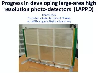
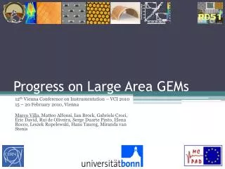
Progress on Large Area GEMs. 12 th Vienna Conference on Instrumentation – VCI 2010 15 – 20 February 2010, Vienna Marco Villa, Matteo Alfonsi , Ian Brock, Gabriele Croci , Eric David, Rui de Oliveira, Serge Duarte Pinto, Elena Rocco, Leszek Ropelewski , Hans Taureg , Miranda van Stenis.

E N D
Progress on Large Area GEMs 12th Vienna Conference on Instrumentation – VCI 2010 15 – 20 February 2010, Vienna Marco Villa, MatteoAlfonsi, Ian Brock, Gabriele Croci, Eric David, Rui de Oliveira, Serge Duarte Pinto, Elena Rocco, LeszekRopelewski, Hans Taureg, Miranda van Stenis
Outline • Gas Electron Multipliers • GEM applications • Motivation for large area GEMs • Single mask photolithography • Improving the polyimide etching • Improving the bottom copper etching • Splicing GEMs • Stretching large area GEMs • Handling large area GEMs • Simulating GEMs • Optimizing the hole geometry • Understanding the charging up • Conclusions & outlooks
Gas Electron Multipliers • GEM properties: • Fast electron signal, no ion tail • Amplification structure independent from readout • Flexible material allows non planar geometries • Possibility to cascade • Cascading GEMs reduces discharge probability
GEM applications (1) • COMPASS (NIM A577 (2007) 455) – tracking for fixed target experiment: • 31 x 31 cm2 active area • X–Y strip readout • Spatial resolution 46 µm • Required rate capability ~ 150 kHz/cm2 • LHCb (2008 JINST 3 S08005) – forward muon triggering: • 24 x 20 cm2 area • Pad readout • Required rate capability • ~ 500 kHz/cm2 • TOTEM (JINST 3 S08007, 2008) – forward tracking and triggering: • 30 cm diameter • Combined strip and pad readout • Required rate capability ~ 1 MHz/cm2
GEM applications (2) • Cylindrical GEM for NA49: • Cylindrical triple GEM detector • π coverage • Based on 31 x 31 cm2 COMPASS GEM foils • 2D cartesian readout wih 400 µm strip pitch • APV25 readout electronics • Truly spherical GEM for X–ray diffractometry: • Spherical conversion gap gives zero parallax error • GEM formed starting from a planar foil • Forming on spherical mold with ~ 20 kg weight applied • Temperature 350 °C for about 24 hours • Conical field cage in the conversion gap • Curved spacers to keep accurate spacing • Planar or spherical readout
Motivation for large area GEMs (1) • Upgrade of TOTEM T1: • 2 telescopes constituted back to back disks • Each disk contains 5 chambers • Chamber overlap allows adjustable disk radius • Triple GEM chambers with ~ 2000 cm2 active area • Chambers based on GEM foils 66 x 66 cm2 • Large area achieved splicing 2 GEMs together • KLOE–2 inner tracker (See E. De Lucia talk): • Cylindrical triple GEM detector • GEMs 96 x 35.2 cm2 active area • Large area achieved splicing 3 GEMs together • No spacers between GEM foils • Cylindrical cathode with annular fiberglass support flanges
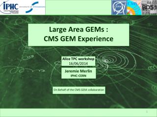
Motivation for large area GEMs (2) • CMS high η region feasibility study: • In the 1.6 < η < 2.1 region the planned RPCs were never installed • Studying the possibility of introducing large area MPGDs • Triple GEM chambers with 97 x 42 cm2 active area • Rate capability sufficient for sLHC conditions • DHCal for ILC (A. White – MPGD 2009): • Modules of 1 m2 active area • Double GEM, thin gaps to reduce total thickness • Muon tomography for homeland security (D. Mitra – IEEE NSS 2009): • Exploits multiple scattering of cosmic muons to locate high–Z materials in cargo • Large area and many readout channels
Technological innovations 1. Double mask photolithography introduces alignment errors ↓ Use single mask 2. Raw material is only 457 mm wide ↓ Splice GEM foils together 3. GEM stretching becomes troublesome ↓ Solutions? 4. GEM handling gets difficult ↓ New tooling and machines
Double mask vs. single mask Single mask photolithography Double mask photolithography 50 µm kapton foil 5 µm copper clad on both sides Photoresist coating, masking, exposure Photoresist development, copper etching Kapton etching Metal etching Second masking, exposure Development, etching, final cleaning
Creating the GEM pattern • 1 – Photoresist lamination: • Base material delivered in 457 mm x 100 m rolls • Piece of base material gets laminated with photoresist • Lamination performed under pressure at 100 – 110 °C • Important to prevent the formation of air bubbles 1 • 2 – Exposition: • Mask kept in place by vacuum system • UV light polymerizes unmasked photoresist • Important to tune the amount of light 2 3 • 3 – Photoresist development: • GEM placed in an oven at 100 °C for a few minutes • Sodium carbonate rinsing removes non polymerized photoresist
Etching the holes in the GEM • Etching the top copper electrode: • Ferric chloride and hydrochloric acid rinsing create the hole pattern on the top copper electrode • Basic bath removes the chromium layer in the holes • Neutralization necessary • Photoresist removal: • Ethanol used to remove the photoresist Potassium hydroxide (KOH) → isotropic • Polyimide etching: • Combining isotropic and anisotropic etching chemistries one can get steep holes • Kapton holes form the mask for bottom copper etching • Kapton profile will be finely tuned at a later stage Ethylene diamine → anisotropic
Etching the bottom copper layer • Etching from the bottom • Etching from the top, using the holes in the polyimide as mask • Ammonium persulfate produces copper thickness variations over large areas → gain inhomogeneity • Chromic acid produces more homogeneous etching • GEM prototype for TOTEM T1 produced with this technique • Copper etching is isotropic → rim appears around the holes → gain stability deterioration • Possible to reduce the rim by slimming down the copper thickness before etching the holes
Splicing GEMs • The base material is only 457 mm wide • Possible to get larger width by splicing GEMs • 2 mm width kapton coverlay on GEMs edges • Pressed and heated up to 240 °C • Seam is flat, regular, mechanically and dielectrically strong • Rate scan with ø 0.5 mm collimated X–ray beam • Behaves normally until the seam • Performance of the rest of the GEM is unaffected
Stretching and handling GEMs • Stretching: • Thermal expansion of a plexiglass frame can be exploited for foil stretching • Stretching bench with load cells connected to meters CERN INFN – LNF • Handling: • Some of the manufacturing steps take place in chemical baths of finite dimensions • A foldable stainless steel portfolio allows handling GEM foils of up to 200 x 50 cm2 • Single mask technology is suitable for mass production with roll–to–roll equipment CERN CERN
Producing the TOTEM T1 prototype 1 – Framing the sliced foils 2 – Making the honeycomb base plane and top cover 3 – Gluing the cathode to the honeycomb frame 4 – Final assembly of all frames 5 – Assembled prototype 1 2 3 4 5
TOTEM T1 prototype performance • Good gas tightness and high voltage stability • Gain lower than standard (double mask) GEM, as expected from wider hole diameter • Hole shape can be tuned by changing the composition of etching chemistry • Energy resolution 22.4 % FWHM/peak for Cu X-rays in Ar:CO2 70:30
Improving the copper etching • In order not to create the rim at all: • Laminate a photoresist layer on the bottom electrode • Apply ~ – 3 V DC to the top electrode → copper becomes inert to etching solution • Etch the bottom copper with chromic acid using the polyimide holes as mask • Go back to polyimide etching for ~ 30 s to get almost cylindrical holes ø 81 µm ø 69 µm • Almost cylindrical hole profile in the polyimide • Perfectly defined holes on both top and bottom electrodes • Spark voltage in air (650 ± 40) V • GEM cleaning assures good robustness against sparks
Single mask GEM performance • Double GEM 10 x 10 cm2 active area • GapD 4.2 mm, gapT = gapI 2.2 mm • ED = ET 2 kV/cm, EI 3 kV/cm • Measurements performed in Ar:CO2 70:30 • Cu X–ray tube (Kα 8.04 keV, Kβ 8.9 keV) • Max. gain ~ 3700 @ ΔVGEM 435 V [few 104 std GEM] • Energy res. 20.8 % FWHM/peak [~ 20 % std GEM] • Fast charging up (14 ± 4) s [~ 30 min std GEM] • Very small charging up 4 % [~ 10% std GEM] • Very robust against sparks
Simulating hole shape effects ø 55 – 55 µm ø 55 – 95 µm ø 95 – 55 µm • Hole shape can be tuned by changing the composition of etching chemistry • Possibility of choosing the optimal shape according to application • Simulation of electric field lines for different geometries • Simulation of electron end point as a function of the geometry 95–55 85–55 75–55 65–55 55–55 55–65 55–75 55–85 55–95
Simulating the charging up • Deposition of electric charges on the polyimide plays an important role in GEMs behavior • Successful simulation of electron charging up in a standard GEM with no gain • Electrons created randomly above the GEM • Electrons drifted and end point recorded • Generation of new field map with deposited charges Time 0 s Time 4 s
Conclusions & outlooks • The single mask technique has proven to be a valid manufacturing technology for GEMs • It was possible to build a large size triple GEM of ~ 2000 cm2 active area which has successfully been tested • Recent refinements of the production method give better control over the hole shape • The technique offers attractive advantages for large area and large scale production • Hole parameters are under study and the optimization process is ongoing
Improving the copper etching • In order not to create the rim at all: • Laminate a photoresist layer on the bottom electrode • Cover the top electrode with gold or tin by galvanic deposition • Etch the bottom copper with chromic acid using the polyimide holes as mask • Strip the photoresist layer, leave the top protection layer ø 91 µm ø 64 µm • The holes on the bottom appear to be very well defined • Difficult to obtain good hermeticity of the top protective layer • The slightest delamination between copper and kapton leads to copper underetching • Gold remains above underetched copper increase spark probability • Need a more efficient way to protect the top electrode