Download
1 / 43
720 likes | 1.71k Views
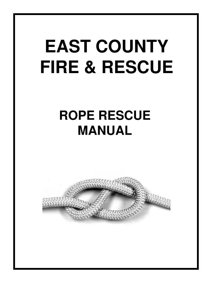
EAST COUNTY FIRE & RESCUE. ROPE RESCUE MANUAL. This manual is meant to be a basic guide for the skills and equipment necessary for an effective technical rescue rope team. Included are commonly used knots, anchor systems, belay and hauling systems.

E N D
EAST COUNTYFIRE & RESCUE ROPE RESCUE MANUAL
This manual is meant to be a basic guide for the skills and equipment necessary for an effective technical rescue rope team. Included are commonly used knots, anchor systems, belay and hauling systems. This manual will reference other publications such as NFPA 1983 Standard on Fire Service Life Safety Rope and System Components And NFPA 1006 Standard for Rescue Technician Professional Qualifications 2000 Edition Compiled by Jim Ludwig Contributors: Dale Dawson Day Durrett Linda Durrett Larry Liehr Pam Maxey
COMMAND AND CONTROL INCIDENT COMMANDER - On scene commander. May or may not be filled by a Technical Rescue Specialist RESCUE GROUP SUPERVISOR - Reports to 1C or OPERATIONS in the incident command system. Preferably a Tech Team Leader or Technician. TEAM LEADER – Decides: Who rigs it What gets rigged Where it gets rigged CONTROL - They give the specific commands. (see next page) BELAYER - Operating the belay or safety line. (first person to be asked if ready!) BRAKEMAN - Operating the main line. (becomes haul team leader during raising ops) EDGEMAN and / or SPOTTER - Maintains positive communications with rescuer during all phases of the rescue. VECTORMAN (S) - Assist with rope movement during specific phases of rope operations. May be assigned to haul team as needed. RESCUER (S) - Person(s) on rope or at risk who performs according to plan the rescue. (last person to be asked if ready before any movement of the system!)
COMMUNICATIONS Often distance or noise will hinder communication. Standardized commands will be used to help insure the proper action at the proper time. Where their use would aid rescue, FRS/GMRS radios may be used for enhanced communication. Use Channel 9 with no privacy codes. (Channels 8 through 14 are FRS frequencies with no license required) Commands Vertical Environment UP (may include rope color, i.e., UP ON BLUE) DOWN STOP Horizontal Environment (i.e. Highline) IN OUT Feedback Repeating the command back to the CONTROL person insures the command was interpreted correctly. BELAY ON? (Statement) BELAY ON! (Response) BELAY OFF? (Statement) BELAY OFF! (Response)
KNOTS & HITCHES NFPA defines rescuer skills NFPA 1006 Standard for Rescue Technician Professional Qualifications 2000 Edition 3-5 Ropes/Rigging.3-5.1 Tie knots, bends and hitches, given ropes and webbing, so that the knots are properly dressed, recognizable, and safety's as required. (a) Requisite Knowledge: Knot efficiency, proper knot utilization, rope construction, rope terminology, and methods of safety, (b) Requisite Skills: Tie representative knots, bends, or hitches for the following purposes: (1) End of line loop (2) Midline loop (3) Securing rope around desired objects (4) Joining rope or webbing ends together (5) Gripping rope
KNOTS & HITCHES CONSIDERATIONS KNOTS ARE SELECTED FOR THEIR SIMPLICITY, STRENGTH, MULTIPLE FUNCTIONS AND USES AND FOR THEIR EASE OF RECOGNITION. • SIMPLICITY IS IMPORTANT WHEN SELECTING A KNOT, KEEPING IN MIND THAT MANY KNOTS ARE TIED UNDER STRESS AND INCLEMENT ENVIRONMENTS. THIS DOES NOT IMPLY, HOWEVER, THAT YOU MAY EMPLOY ANY KNOT THAT COMES TO MIND. THE UNIT HAS "PRE-SELECTED" APPROVED KNOTS, HITCHES AND BENDS THAT HAVE BEEN TESTED AND MEET STRICT CRITERIA. • STRENGTH IS THE MOST IMPORTANT ASPECT WHEN SELECTING A KNOT FOR THE APPLICATION. MANY KNOTS WOULD PROBABLY WORK, BUT MANY WOULD NOT HAVE THE SAME EFFICIENCY. FOR EXAMPLE: A DOUBLE FIGURE 8 KNOT IS ~ 5% STRONGER THAN A SINGLE LOOP FIGURE 8, AND 15% STRONGER THAN A BOWLINE. • THERE ARE OVER 15 KNOTS THAT THE TECHNICAL RESCUE TEAM USES IN ITS SYSTEMS AND RIGGINGS. THERE ARE MANY MORE THAN THAT AVAILABLE IN THE RIGGERS TOOLBOX; HOWEVER, IT IS IMPORTANT TO REMEMBER THAT WHILE MANY KNOTS DO THE SAME THING, KEEPING THE SYSTEMS "SIMPLE" IS CRUCIAL THIS ALLOWS THE SAFETY OFFICER TO RAPIDLY CHECK THE SYSTEM, QUICKLY IDENTIFYING KNOTS THAT ARE TIED CORRECTLY, BECAUSE OF FREQUENT TYING AND USE OF A SELECT FEW KNOTS. • SELECTION • KNOTS ARE SELECTED FOR THEIR "EFFICIENCY". THIS MEANS THAT SOME ARE MORE EFFICIENT THAN OTHERS. AN EXAMPLE OF THIS RATING IS A ROPE THAT IS RATED AT 50% EFFICIENT. THIS MEANS IF THE ROPE IS RATED AT 9000#, AND A FIGURE 8 KNOT IS TIED INTO IT, THE ROPE IS NOW ONLY 4500# RATED. • SOME KNOTS ARE SELECTED BECAUSE THEY ELIMINATE EQUIPMENT, SUCH AS CARABINERS, OR PROVIDE MULTIPLE DIRECTIONS OF LOADING. OTHERS ARE SELECTED FOR THEIR SIMPLICITY IN TYING AND VERIFYING, AND UNTYING WHEN LOADED.
KNOTS & HITCHES FIGURE 8 "FAMILY” • THESE KNOTS ARE USED FOR TYING PERSONNEL INTO SYSTEMS, ATTACHING RIGGING TO ANCHORS, AND ROPES TO LITTERS. THEY ARE TYPICALLY 75-80% EFFICIENT. A FIGURE 8 FOLLOW THROUGH IS USED TO ATTACH TWO ROPES TOGETHER, OR FOR TYING PERSONNEL DIRECTLY INTO A SYSTEM. THIS FAMILY OF KNOTS IS THE MOST POPULAR OF ALL THE KNOT CHOICES IN RESCUE WORK. BOWLINE • THIS KNOT IS ALSO USED FOR TYING PERSONNEL DIRECTLY INTO A SYSTEM. IT IS ALSO USED WHEN A HEAVY LOAD IS EXPECTED ON A KNOT AND NEEDS TO BE EASILY UNTIED. BECAUSE OF THIS FEATURE, A BACK-UP OR SAFETY OVERHAND KNOT MUST BE USED. THIS KNOT IS ONLY 65% EFFICIENT. WATER KNOT (FOLLOW THROUGH) • THIS KNOT IS USED IN CONJUNCTION WITH WEBBING. IT IS EASILY SLIPPED, AND THEREFORE, A OVERHAND SAFETY MUST ALSO BE USED. THE KNOT IS THE PREFERRED CHOICE WHEN TYING RUNNERS OR WHEN CREATING ANCHORS MADE OF TUBULAR WEBBING. IT IS 80% EFFICIENT. DOUBLE FISHERMAN'S (BARREL KNOT) • THIS KNOT IS USED WHEN TYING TWO PIECES OF ROPE OR CORDAGE TOGETHER. IT IS THE PREFERRED KNOT WHEN CREATING PRUSIKS. THERE IS NO PUBLISHED EFFICIENCY RATING ON THIS KNOT. MUNTER HITCH • A HITCH RATHER THAN A KNOT, THIS IS USED TO BELAY PERSONNEL OR GEAR, AND ALSO FOR PERSONAL RAPPELLING. THIS HITCH IS NOT TO BE USED FOR RESCUE LOADS OR MORE THAN TWO PEOPLE.
Basic Figure 8 Can be used as a “stopper” or the start of a Figure 8 Follow-Through Figure 8 On a Bite with Overhand Safety Also a finished Figure 8 Follow-Through Double Figure 8 with Overhand Safety
The Butterfly knot is used to put a loop in the middle of a line that will take load in both directions The Double Fisherman’s Knot is used in making Prusik cords or can be used to join two ropes The Munter Hitch can be used for lowering a load, or self-lowering
Overhand Knot Water Knot WEBBING KNOTS An overhand knot followed through from the opposite direction makes a water knot. Can be used to join two pieces of webbing or to make a loop that can be used as an anchor.
Bowline Clove Hitch Clove Hitch from Webbing UTILITY KNOTS Not used for life safety
ANCHORS NFPA 1006 Standard for Rescue Technician Professional Qualifications 2000 Edition Anchor points................................................3-5.2, 4-1.1 Definition...............................................................1-4.3 Anchorsystems3-5.2 to 3-5.5, 3-5.7, 4-1.3, 4-1.7, Table A-1-3 Definition...............................................................1-4.4 Fixed rope....................................................4-1.9, 4-1.10 Multiple point......................................................... 4-1.1 Definition...............................................................4.4.1 Single point.............................................................3-5.2 Definition...............................................1-4.4.2, A-1-4.4.2 CONSIDERATIONS ANCHOR CHOICES CAN BE PLENTIFUL OR HARD TO COME BY IN RESCUE WORK. THE FIRST CONSIDERATION THAT MUST BE CALCULATED IS THE LOCATION OF THE VICTIM OR THE "VECTOR" IN WHICH THE LOAD IS TO BE LOWERED OR RAISED FROM. ONCE THAT LOCATION HAS BEEN DETERMINED, ANCHOR SELECTION CAN BEGIN. ANCHOR STRENGTH • ALL ANCHORS MUST BE "BOMBPROOF". ALL ANCHORS MUST MEET OR EXCEED THE 15:1 SAFETY MARGIN ESTABLISHED BY THE NFPA • THE "STRONGEST" ANCHOR SHOULD BE THE SAFETY ROPE LINE, ALLOWING FOR A FAILED MAIN AND THEREBY SHOCK LOADING THE SAFETY ANCHOR POINT. • THE MAIN ANCHOR NEEDS TO HAVE ROOM FOR A RAISING SYSTEM AND A LOCATION FOR HAULERS TO PULL TOO. THEREFORE, IT IS USUALLY PLACED BACK FROM THE EDGE AND STILL IN LINE WITH THE SAFETY ANCHOR. • THE SAFETY IS USUALLY PLACED NEAR THE EDGE (BUT STILL AT A SAFE DISTANCE) TO ALLOW THE STATION OPERATOR CLEAR VIEW OF THE OPERATION AND, IF NEEDED, A POTENTIAL EDGE PERSON TO COMMUNICATE WITH THE RESCUERS. • GUARDRAILS, VEHICLES, TREES, LARGE ROCKS, ETC ARE COMMONLY USED AS BFTS OR BFR'S. DO NOT USE TRAILER HITCHES OR TOW HOOKS AS ANCHOR POINTS OFF VEHICLES. USE MAIN FRAMES OR AXLES FOR STABLE POINTS OF ATTACHMENT.
ANCHOR TYPES TENSIONLESS ANCHOR Minimum 3 wraps, more if surface is smooth Aligns with direction of pull Same strength as rope because no load on knot Using a tree having a rough surface
ANCHOR TYPES Webbing Anchors Wrap once – Least desirable because load is on knot Wrap two, pull one – better because load is taken off knot Wrap three, pull two – best because load is off knot and web is doubled for strength Tubular Webbing is rated 4000 lbs
LOAD SHARING ANCHOR Viewed from load Viewed from anchor Used where strength from multiple anchors is required The load is distributed among the anchor points
MAIN LINE ROPE BAG Recommended equipment (CCFD6 list) Anchor strap 20' 1 eachWebbing (black) 25' 1 eachCollection Plate 1 each W/ carabineerBrake rack 1 each W/ carabineerPrusiks minding pulley 1 each W/ carabineer Prusiks - long & short 1 setLoad releasing hitch 1 each 9 mm rope 30’ 1 each Carabineer 2 each Prusiks - long & short1 set Knee pads 1 setRope 1/2" 200' 1 each
BELAY BAG Equipment Helmet 200’ ½” Rope Anchor Plate w/Caribiner Load Releasing Hitch w/Caribiner Prusik Minding Pulley w/Caribiner and 2 Prusik cords 3 Slings of different lengths Edge Protector Rescuer Harness w/ Caribiner and 2 Prusik Cords
LOWERING A LOAD/RESCUER “RPM”, stored in the Main Line Rope Bag, is the basis for the main line lowering / haul system. It consists of an anchor plate with: Ladder Rack Prusik Minding Pulley Mariner’s Load Releasing Hitch Also stored for convenience is a simple pulley and two Prusik cords. Note the orientation of the carabiners on all of the devices. The opening should be toward the load so that vibrations in the rope will not vibrate the collets open.
LADDER RACK Ladder Rack shown with the Main Line Rope threaded over all six friction bars. In practice, fewer bars are needed to control the average load. These bars can be easily removed while under load. Ladder Rack tied off
SAFETY LINE A Safety Line using a Prusik Minding Pulley and two Prusik Cords This safety line could be easily converted to a haul system.
To quickly stop, pass the free and of the rope between the load line and the 8 SELF LOWERING Belaying is the preferred lowering method. If rapid access to a patient is required, then rappelling is an alternative. To fully lock off the 8, take a bight and pass it through the top of the 8 and secure it to the main line with a carabiner
SELF LOWERING A Munter Hitch can be used for self lowering in a low angle situation. It can only create enough friction for a single rescuer load. The load line in this picture is shown in line with the anchor rope. The tail on the left is used to control the amount of friction necessary to lower the load. It is not as convenient to tie off as the rescue 8.
RAISING A RESCUE LOAD • CONSIDERATIONS • When rigging a rescue load, the technical rescue team complies with the NFPA standards and guidelines for rescue loads. The considerations and assumptions are: • Each person, regardless of actual weight, is calculated at 300#. For example, (2) persons (victim and rescuer), with full gear is 600#. • Each hauler that pulls on the mechanical advantage is capable of pulling 60# of effort. This is regardless of their actual pulling ability, that way if someone pulls more than their 60#; it is not compromising the systems capability. • That a (2) rope system is always employed during a high angle environment. That a 15:1 safety margin is used on all systems. • LOADS • • As mentioned above, each rescuer and or person weighs 300#. This is based on the 15:1 safety margin rule that was also discussed. The unit uses a 1/4' 9000# rated low stretch (static) rope. • • If 2 persons are on the rope, then simply the load is figured at 600#. If you were to divide 9000# by 600#, the answer would be 15. • • When rigging a raising system, the system will already (usually) be rigged in a lowering fashion. This is assuming that we had to lower someone down to the victim, and now we are "switching" to a raise. With this assumption, the load is being carried by the "Main" and being backed up by a "potential" belay called the "safety" line. The steps are: • • Lock off the brake rack on the "Main" and set the prusiks on the "Safety" line. The remaining steps are for the "main" line only as the "safety" is already rigged for a raise. • Using the "RPM" as a prompt, it is obvious that the "R" in the "RPM" is being used. We need to release the rack out of the system. To do this we need to attach the tandem prusiks, which are pre-rigged and attached to the load releasing hitch, to the load line, out ahead of the brake rack. Once this is finished, set the prusiks. • Now unlock the brake rack and lower any "load" onto the prusiks. This should allow the rack to go slack and be allowed to be removed from the rope. Let the brake rack hang on the King plate, as we may need it later. • All of the "load" should now be on the tandem prusiks, so run the "main" rope through the prusik minding pulley that is attached to the "RPM" and continue taking the rope down towards the "load". Attach another single triple wrap prussic to the rope that is under load and clip a rescue carabiner and prusik minding pulley into this newly attached prusik. • Run the slack rope through this pulley and have haulers ready for hauling. • We have just created a 3:1 mechanical advantage.
HAUL SYSTEMS Pulley systems are rated as to their mechanical advantage and to whether they are “simple” or “compound”. In a simple pulley system, all of the traveling pulleys in the system move toward the anchor at the same speed. A compound system has two or more pulley systems acting on each other. Static Kernmantle rope creates internal friction when bent due to the fibers in the kern (core) rubbing against each other. The smaller the radius of the bend, the more friction. It is best to use the largest diameter pulley available to reduce that friction. The ratio of rope diameter to pulley diameter will determine the loss in mechanical advantage of a system according to the following table. In a simple 3:1 system with 4” pulleys, the effective M.A. would be 2.85:1. If 2” pulleys were used, the effective M.A. would be 2.57:1. In the 4:1 simple system shown using one 4” pulley at the anchor and two 2” pulleys at the load, the effective M.A. would only be 3.41:1.
The end of the rope is Tied to the load so the M.A. is an odd number Two pulleys moving With the load, end of The rope is tied to the Anchor makes it an Even number M.A. HAUL SYSTEMS The number of pulleys + one gives the mechanical advantage in a simple system. If the end of the rope is tied to the load, the number will be odd. These are both “simple” systems. 4:1 Haul system Two Pulleys
HAUL SYSTEMS In a simple system with the end of the rope at the anchor, each pulley that moves with the load adds 2 to the M.A. therefore, this system is a 6:1. Factoring in the friction loss with 4” pulleys, the effective M.A. would be 5.3. If 2” pulleys were used, that would drop to 4.15:1. The drawback to this method of achieving pulling strength is the amount of rope it takes. In this example, a 300 foot rope would only give a 50 foot reach.
HAUL SYSTEMS In the simple 3:1 system on the left, a 300 foot rope would have a reach of 100 feet. The system on the right, is also a 3:1 and is called a Z-rig because if viewed on its side, the rope forms the letter Z. The advantage to this configuration is maximizing the use of rope. A 300 foot rope could obtain a reach of 260 feet, although the prusiks on the load line would have to be reset every 10 feet of pull on the load line.
COMPOUND AND COMPLEX SYSTEMS On the left, a 2:1 system pulling on a 3:1 system becomes a compound 6:1 system In the center, a 3:1 system pulling on a 3:1 system becomes a compound 9:1 system. On the right, connecting the upper right pulley to the rope of the left pulley with a prusik, it becomes a complex 11:1 system.
LOWERING TO HAUL TRANSITION • After lowering the rescue team to the patient, the haul team needs to convert their rigging from lowering to hauling as quickly as possible so as to not delay the rescue operation. This can be done without removing load from the rope. • After lowering, put a pulley on the main line. • Attach that pulley to the load releasing hitch. • Install two prusiks from the load releasing hitch to the main line. • Let those prusiks take the load from the ladder rack. • Remove the rope from the ladder rack and add a second pulley. • Attach the second pulley to the main line with prusiks. • You now have a 3:1 simple haul system. (Z-Rig)
PASSING A KNOT Often two ropes will be joined together and when the knot reaches a pulley, there has to be a means to pass the knot around it. Using the 4:1 piggyback system, connect to the haul line using 2 triple-wrap Prusic cords. Pull the haul line with the piggyback far enough that the knot can be passed around the pulley, then tie off the piggyback. Remove the main line Prusics, split the pulley and move the knot to the other side. When the pulley is securely attached and safety checked, begin hauling with the main system until the Prusic cords can be removed from the piggyback system.
F=W x h l Where F = force to pull W = weight of object h = height of slope l = length of slope On a 30 degree slope, the length of the slope is twice the height it rises Force needed to keep the ball from rolling down the hill=150# Gravity pulls the ball down the slope with a force of 150# Force against The incline Force of Gravity=300# SELECTING A HAUL SYSTEM The illustration demonstrates the principal of an inclined plane. The angle is 30 degrees, which is the maximum for low angle rescue. A ball is placed on a slope and the forces acting on it are described in the illustration. A rule of thumb is to assume each rescuer weighs 300 pounds along with a victim of the same weight. 3 rescuers on a litter, would be a total of 1200 pounds. It would take a pull of 600 pounds to pull them up the slope. Using a 15:1 safety factor for the rope, 15 X 600 = 9000 pounds, the rated 5/8 inch rope strength. Each haul team person is rated to pull 60 pounds so it would take 10 people to haul the load up the slope. Using a 3:1 Z-rig would allow 4 people to haul the load. (600# / 3 = 200#, 200# / 60# per person = 3.3) By putting another 2 pulleys in the haul system to create a compound 9:1 mechanical advantage, 2 people could haul the load, although more slowly because it takes more time to reset pulleys.
RIGGING A LITTER Litter with webbing and straps in place Patient on backboard laid in litter with webbing harness on his legs
SECURING THE PATIENT The orange webbing secures the patient and backboard so that they cannot slide down the litter Lacing the black webbing secures the patient to the litter The last step will be to fasten the
SECURING FINISHED Crossing the seat belts and fastening them completes the packaging of the patient. The wide blue straps will attach to the haul system. The rescuers will attach their harnesses to the litter with other straps Note the footrest at the bottom of the litter
THE NEXT 9 SLIDES SHOW HOW TO MAKE A TEMPORARY HARNESS FROM WEBBING Tuck the middle of the webbing into the waistband
Bring each end down and between the legs and out to the sides
Bring the ends around and through the part tucked into the waistband
Pull on the ends and let the center part come out of the waistband
Attach a carabiner as shown. This can be used to secure A patient in a stretcher as well as provide a means to lift a short distance.