Download
1 / 10
100 likes | 260 Views
Integrated, Self-learning DC-DC Converter for Portable Applications Neeraj Keskar Advisor: Prof. Gabriel A. Rincón-Mora Georgia Tech Analog Consortium Review Analog Integrated Circuits Laboratory School of Electrical and Computer Engineering Georgia Institute of Technology Fall, 2003.

E N D
Integrated, Self-learning DC-DC Converter for Portable Applications Neeraj Keskar Advisor: Prof. Gabriel A. Rincón-Mora Georgia Tech Analog Consortium Review Analog Integrated Circuits Laboratory School of Electrical and Computer Engineering Georgia Institute of Technology Fall, 2003
Motivation • Significant dependence of converter frequency response on passive components • Tolerances in capacitor ESR, ESL values • Variations in inductor, capacitor values per design • IC solution for frequency compensation required because • Reduction in design time • Reduction in part count • Reduction in board size, cost • Ease of design • Need to have IC solution that will give frequency compensation independent of external components • Various techniques in literature are investigated next
Method 1: Masking Unreliable Capacitor ESR zero Block schematic with feedforward path Loop gain including feedforward path • Introduce artificial, reliable feedforward zero • Feedforward path introduces reliable zero at frequency zFF • Zero at zFF dominates ESR zero in loop gain • Similar application in hysteretic control
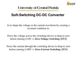
Method 1a: Modified Hysteretic Control • Modified voltage hysteretic control • Voltage hysteretic control • Inherently stable • Fast response • Simple control • Cap ESR rC affects performance and stability • Feedforward path RF-CF • LCR filter masked • Other benefits of hysteretic converter maintained • Applicable only to buck converter
Method 2: Elimination of RHP Zero in Boost/Buck-boost converter • Constant capacitor discharge time • Auxiliary switch diode freewheels • inductor current • Total capacitor discharge time 0-t2 • Freewheeling time controlled to keep • t2 constant • Gains • RHP zero eliminated, simple control • Filter poles independent of Q-point • Drawbacks • Inductor current ↑, I2R power losses ↑ • Four switches, same fsw-Switch losses ↑
Method 3: Masking RHP Zero in Boost/Buck-boost converter • Masking RHP zero using capacitor ESR • Feed back output voltage peak with no “voltage dip” – no RHP zero • ESR large enough to overcome capacitor voltage drop • RHP zero masked out from loop gain • Large ESR required – voltage ripple worsened • High frequency feedback loop – noise issues
Method 4: Compensating for LCR Filter Variations • Constant LCR load control • Auxiliary controller & LC filter present constant LCR impedance • Effective impedance seen by compensator is independent of LCR • Positive feedback loop L can introduce additional instability • Inapplicable to boost/buck-boost converters
Method 5: Grid Point Control • Multiple operating point control • Multiple possible quiescent points based on various LCR values • Suitable stable operating point chosen per actual LCR values • Stable operation obtained over a wide range of LCR values • Tedious technique to implement • Instability possible during changeover between two points
Comparison of Stabilizing Techniques Conclusion • Hysteretic control based scheme to be extended to boost converter
Future Work Self learning controller design ideas • Extension of hysteretic control based schemes in boost converter – expected benefits • Simpler control • Fast transient response • Independence of stability from LCR parameters Controller design challenges • Design complexity and ease of use • System size and cost • Application under wide operating conditions • Methodology to be possibly scalable to different converter types