Download
1 / 21
280 likes | 813 Views
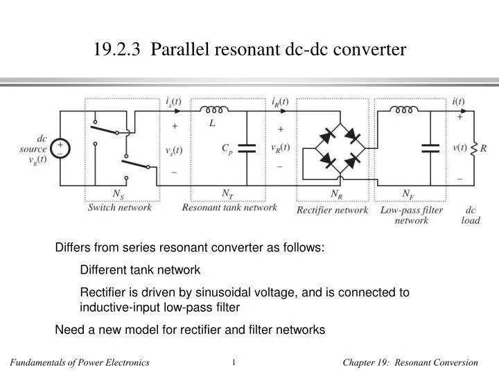
19.2.3 Parallel resonant dc-dc converter. Differs from series resonant converter as follows: Different tank network Rectifier is driven by sinusoidal voltage, and is connected to inductive-input low-pass filter Need a new model for rectifier and filter networks.

E N D
19.2.3 Parallel resonant dc-dc converter • Differs from series resonant converter as follows: • Different tank network • Rectifier is driven by sinusoidal voltage, and is connected to inductive-input low-pass filter • Need a new model for rectifier and filter networks
Model of uncontrolled rectifierwith inductive filter network Fundamental component of iR(t):
Effective resistance Re Again define In steady state, the dc output voltage V is equal to the average value of | vR |: For a resistive load, V = IR. The effective resistance Re can then be expressed
Equivalent circuit model of uncontrolled rectifierwith inductive filter network
Dc conversion ratio of the PRC At resonance, this becomes • PRC can step up the voltage, provided R > R0 • PRC can produce M approaching infinity, provided output current is limited to value less than Vg / R0
Comparison of approximate and exact characteristics Series resonant converter Below resonance: 0.5 < F < 1 Above resonance: 1 < F
Comparison of approximate and exact characteristics Parallel resonant converter Exact equation: solid lines Sinusoidal approximation: shaded lines
19.3 Soft switching • Soft switching can mitigate some of the mechanisms of switching loss and possibly reduce the generation of EMI • Semiconductor devices are switched on or off at the zero crossing of their voltage or current waveforms: • Zero-current switching: transistor turn-off transition occurs at zero current. Zero-current switching eliminates the switching loss caused by IGBT current tailing and by stray inductances. It can also be used to commutate SCR’s. • Zero-voltage switching: transistor turn-on transition occurs at zero voltage. Diodes may also operate with zero-voltage switching. Zero-voltage switching eliminates the switching loss induced by diode stored charge and device output capacitances. • Zero-voltage switching is usually preferred in modern converters. • Zero-voltage transition converters are modified PWM converters, in which an inductor charges and discharges the device capacitances. Zero-voltage switching is then obtained.
19.3.1 Operation of the full bridge below resonance: Zero-current switching Series resonant converter example Operation below resonance: input tank current leads voltage Zero-current switching (ZCS) occurs
Tank input impedance Operation below resonance: tank input impedance Zi is dominated by tank capacitor. Zi is positive, and tank input current leads tank input voltage. Zero crossing of the tank input current waveform is(t) occurs before the zero crossing of the voltage vs(t).
Switch network waveforms, below resonanceZero-current switching Conduction sequence: Q1–D1–Q2–D2 Q1 is turned off during D1 conduction interval, without loss
ZCS turn-on transition: hard switching Q1 turns on while D2 is conducting. Stored charge of D2 and of semiconductor output capacitances must be removed. Transistor turn-on transition is identical to hard-switched PWM, and switching loss occurs.
19.3.2 Operation of the full bridge below resonance: Zero-voltage switching Series resonant converter example Operation above resonance: input tank current lags voltage Zero-voltage switching (ZVS) occurs
Tank input impedance Operation above resonance: tank input impedance Zi is dominated by tank inductor. Zi is negative, and tank input current lags tank input voltage. Zero crossing of the tank input current waveform is(t) occurs after the zero crossing of the voltage vs(t).
Switch network waveforms, above resonanceZero-voltage switching Conduction sequence: D1–Q1–D2–Q2 Q1 is turned on during D1 conduction interval, without loss
ZVS turn-off transition: hard switching? When Q1 turns off, D2 must begin conducting. Voltage across Q1 must increase to Vg. Transistor turn-off transition is identical to hard-switched PWM. Switching loss may occur (but see next slide).
Soft switching at the ZVS turn-off transition • Introduce small capacitors Cleg across each device (or use device output capacitances). • Introduce delay between turn-off of Q1 and turn-on of Q2. Tank current is(t) charges and discharges Cleg. Turn-off transition becomes lossless. During commutation interval, no devices conduct. So zero-voltage switching exhibits low switching loss: losses due to diode stored charge and device output capacitances are eliminated.