Download
1 / 28
280 likes | 389 Views
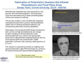
An Integrated Program for GBT Focal Plane Array Development. Steven White Based on discussions with: Rick Fisher, John Ford, Matt Morgan, Roger Norrod, Kamaljeet Saini, Amy Shelton, Richard Prestage, John Webber, and others. Summary.

E N D
An Integrated Program for GBT Focal Plane Array Development Steven White Based on discussions with: Rick Fisher, John Ford, Matt Morgan, Roger Norrod, Kamaljeet Saini, Amy Shelton, Richard Prestage, John Webber, and others
Summary • A pathfinder focal plane array (FPA) frontend is the necessary first step in an integrated development program. • K-band is the appropriate frequency, for reasons which will be outlined. • We have the necessary resources and expertise ($, more importantly appropriate staff effort) ready and eager to go. • We need to start now to demonstrate results within ~ 2 years (production use in ~3 years).
IntegratedFPADevelopment Program • The Science Case is the primary driver for frequency selection and detailedspecifications. • Development Program Components • Frontend (EM Components, Cryogenics, HEMT Amp, Calibration, Downconversion) • Digitization and IF Transmission • Spectrometer • Software • Scientific desires must be tempered by technical realities and costs of each component . • True measure of a successful program for the GBT: • Competitive instrumentation installed on short time scales and in production use by external observers.
Instrument Development Realities • GBT Spectrometer • ~5 year development time with an additional 5 year integration time. • Finally debugged August 2007 • Ka-band Receiver • Extensive refurbishments required for each of three successive observing seasons • HARP/ACSIS FPA program on JCMT • HARP – 16 pixel 345GHz frontend • ACSIS – 16 x 2 x 1GHz spectrometer backend • Similar specifications and logistical challenges to our proposed system • ~10 year development time • IF distribution became critical path item • Commissioning FE/IF/BE simultaneously is enormously complicated! • Solution • Select challenging but realistic component deliverables. • Develop on 1-2 year timescales. • Integrate each new component into the production system to allow immediate, productive astronomy.
Development Path: 1st Step • Frequency Selection • λ < K-band: physically too large for Gregorian focus (needs beam-forming array at prime focus). • λ = Q, W-band: existing IF capacity inadequate; upgrade path unknown. • λ = Q, W-band: telescope performance still under development (should be delivered on 2-3 year timescales, but not a given). • λ = W-band: significant detector and other R&D development required. • Where is GBT Unique?
K-Band Advantages • A scientifically exciting but technically realistic focal plane array. • Can do production science with existing IF system and spectrometer. • Parallel and collaborative spectrometer developments possible but not critical. • Realize cost savings and enhanced performance for future expansion of instrument.
K-Band Advantages • Develop on 1-2 year timescales • Integrate each new component into the production system to allow immediate, productive astronomy. • Technical staff available for two years and ready to begin. • Frontend: minimal R&D effort required. • Current capability to demonstrate a prototype within one year. • Concurrent software development with a usable instrument within 2 years.
K-band FPA Deliverables • Frontend • Cryogenic Package • Modular Downconverter • Modular Noise Calibration • Mechanical Packaging • Software • Package for Engineering and M&C • Package for data analysis
Future FPA Developments • Significantly enhanced spectrometer with this new array and existing IF system. • New digital I.F. distribution system. • Expanded focal plane array (perhaps at a different frequency) • Phased, expandable software development to match hardware capabilities.
Spectrometer • We have a new approach – CICADA program • Configurable Instrument Collaboration for Agile Data Acquistion • Collaboration between GB, CDL, UC Berkeley CASPER group, WVU, University of Cincinnati, others • Initial production instrument: pulsar backend (“Scott’s Dream Machine") • Design of a 2GHz bandwidth spectrometer already identified as a deliverable for FY2008 • Construction could commence in FY2009 given resources • Excellent candidate for external funding: • Correct technology area (innovative hardware / networking / computing) • University collaborations => “prototype” backends are under development; new Spectrometer development should start in Fy2009
IF System • Current analog IF system limits expansion. • Analog modulators costly with increased complexity due to stability requirements. • Downconversionscheme limits bandwidth • Digitization at antenna with filtering/compression schemes probable solution for IF transmission. • Commerical technology advancements in digital transmission reduces cost and increases performance. • Development in this area is extremely active, driven by SKA and SKA-pathfinder initiatives
Software • Similar systems do exist at other telescopes. • Challenge in software is to transfer approach or actual implementation to your specific telescope. • We will certainly leverage work done elsewhere, and collaborate with other groups. • Using existing GBT Spectrometer makes problem much more tractable (many GBT-specifics already solved). => Software development is an integral part of FPA program addressed early in the project.
Development Path Summary • Processing software: issues well understood • Backend: current system can accommodate a modest array (at K-band), issues and upgrade path well understood. • I.F. system: current system can accommodate modest array, upgrades premature at this time • Frontend: Proposed K-band. • A pathfinder focal plane array (FPA) frontend is the necessary first step in an integrated development program.
K-band FPA Summary • K-band is the appropriate frequency. • We have the necessary resources and expertise ($, more importantly appropriate staff effort) ready and eager to go. • We need to start now to demonstrate results within ~ 2 years (production use in ~3 years)
Backup Slides Backend Data Transmission System Telescope Performance Weather
Backend Strawman Design • Strawman Specifications • 3 GHz analog bandwidth • 6 GS/s • 8 bit ADC, 6 bit ENOB • 183 KHz resolution@ 3 GHz bandwidth (16K channels) • 80 millisecond minimum integration time • 200 MB/s aggregate data rate to disk for 122 IF channels
Backend Strawman Design • Technology Approach • Off the shelfADC chips • FPGA DSP hardware • Off the shelf Data Collection Computer Systems • Optional locations • Receiver room • Equipment room
Backend Strawman Design • Cost • $20K/pixel sampler and DSP costs(2 channels) • $2.44M for 61 pixels, scales linearly with # pixels • $30K Data collection and storage computers • $70K data transmission to disks (all DSP at front end) • 6 FTE-years effort (3 people, 2 years) • Total $3.3 million.
Data Transmission Systems EVLA and ALMA Data Transmission Systems are not appropriate • GBT needs 4 bit samplers • EVLA 3 bits • ALMA 2 bits • ALMA and EVLA multiplexing too complex and expensive for GBT => Advantages in allowing technology to develop.
Azimuth Track Replacement Project • Field work completed on Monday 3rd September to specification, on schedule and within budget • Now in the process of developing new pointing model; initial results extremely promising. Local tilt (pitch) of the antenna as measured by inclinometers mounted on the elevation axle. Both large and small scale track effects are significantly reduced. Very first observation after outage complete. Measured pointing offsets (3”, 1.5”) in (az,el).
Surface Performance • OOF technique can easily measure large-scale wavefront errors with accuracy ~ 100µm • Large scale gravitational errors corrected via OOF look-up table • Benign night-time rms ~ 350µm • Efficiencies: 43 GHz: ηS = 0.67 ηA = 0.47 90 GHz: ηS = 0.2 ηA = 0.15 • Now dominated by panel-panel errors (night-time), thermal gradients (day-time)
Atmospheric Absorption and Emission (excellent) (mediocre) lowers the SNR exp(-) / Tsys Slide Courtesy Jim Condon
Observing Limits (accept/reject) • Atmospheric efficiency • Atmospheric stability • Absolute hour angle • Zenith angle < 85 deg • Tracking flux error < 10% Atmospheric efficiency Slide Courtesy Jim Condon
Stringency 1 / (fraction of time OK) Stringency measures the difficulty of scheduling an observation on the GBT. It depends strongly on the observing frequency and also on the source elevation at transit. Slide Courtesy Jim Condon