Download
1 / 26
260 likes | 267 Views
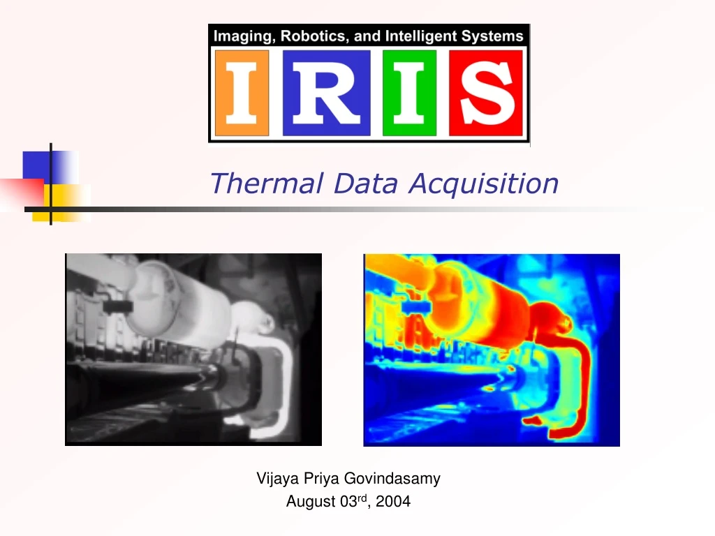
Thermal Data Acquisition. Vijaya Priya Govindasamy August 03 rd , 2004. Outline. Objective Previous Work Thermal Data Acquisition Real Thermal Images Temperature Measurement using IR thermometer Future Work. Objective.

E N D
Thermal Data Acquisition Vijaya Priya Govindasamy August 03rd, 2004
Outline • Objective • Previous Work • Thermal Data Acquisition • Real Thermal Images • Temperature Measurement using IR thermometer • Future Work
Objective • The aim of this task is to obtain real thermal images and corresponding temperature values of under vehicle automotive parts with respect to time. • The temperature data is used in simulation of synthetic thermal images using the software MuSES • Possible ways of comparison between real and simulated thermal images will be analyzed
Previous Work • Thermal Image Acquisition • Thermal images of under the hood components were acquired using the Indigo Omega camera • Results were not satisfactory since the components like intake manifold does not show any significant variation in temperature with respect to time
Results - 0 minute and after 10 minutes – Gray scale and color coded
Results - after 20 minutes Intake manifold and Muffler – Gray scale and color coded
Under the Hood Components Visual Image of the automotive parts
Points to be Considered • Intake manifold just delivers the outside air and fuel mixture • Temperature rise cannot be significantly noted • Parts of interest would be engine block, catalytic converter or muffler • To obtain a complete thermal image of the entire system the vehicle has to be jacked up
Acquisition of Thermal Images • A complete thermal sequence of the under vehicle automotive components was acquired • Thermal data of the under vehicle chassis was obtained using the Indigo Omega camera and Raytheon Infrared Camera • The vehicle used for acquiring data is Dodge RAM 3500 IRIS Van. • All the systems were mounted on a tripod and were never disturbed during the acquisition process.
Hardware Setup for Acquisition Setup for Data Acquisition and IRIS Van
Thermal Sequence I - Catalytic converter and Muffler Section Visual Image of the Under Vehicle section involving Catalytic converter and Muffler • Thermal Video sequence of the section shown above – Indigo Omega Camera • Thermal Video sequence of the section shown above – Raytheon IR Camera
Thermal Sequence II - Muffler and Drive shaft Section Visual Image of the Under Vehicle section involving Muffler and Drive Shaft • Thermal Video sequence of the section shown above
Thermal Sequence III – Exhaust Pipe and Muffler Section Visual Image of the Under Vehicle section involving Exhaust Pipe • Thermal Video sequence of the section shown above
Thermal Sequences with Unusual Objects in Under Vehicle Chassis Visual Image of Real Muffler connected to the exhaust system • Thermal Video sequence of the section shown above
Thermal Sequences with Unusual Objects in Under Vehicle Chassis Contd.. Visual Image of the Muffler attached to the under vehicle chassis • Thermal Video sequence of the section shown above
Thermal Sequences with Unusual Objects in Under Vehicle Chassis Contd.. Visual image of real muffler and the attached muffler in the same scene • Thermal Video sequence of the section shown above
Previous Work contd.. • Simulation of thermal images • Thermal models were simulated in MuSES using the CAD models or LASER scanned and reconstructed models. • The properties assigned were assumptions.
Previous Work contd.. MuSES Interface detailing all the sub tabs
Temperature Measurement using Raytek IR thermometer Raytek Mx4+ IR thermometer • The thermometer includes the following features • Laser Sighting • Adjustable Emissivity • Data logger (100 points) • Graphic Display • Windows-based Software • MAX , MIN, DIF and AVG temperature values • The MX4+ can be used to monitor, graph, and record real-time temperature changes with the DataTemp software
Results of Temperature Measurement Point of temperature measurement – catalytic converter Graph showing the temperature of the catalytic converter
Results of Temperature MeasurementContd.. Point of temperature measurement – muffler Graph showing the temperature of the muffler
Results of Temperature MeasurementContd.. Point of temperature measurement – rear pipe / exhaust pipe Graph showing the temperature of the rear pipe of muffler
Simulation of Under Vehicle chassis using real temperature data Simulated thermal model of the under vehicle automotive components
Future Work • Continue acquiring real thermal images of under vehicle automotive parts under different environmental conditions • Obtain a real time temperature curve using the PTZ device • Simulate thermal models based on the temperature curve and environmental conditions