Download
1 / 17
180 likes | 437 Views
Vasilis A. Riziotis , Dimitris I. Manolas, Spyros G. Voutsinas National Technical University of Athens School of Mechanical Engineering Fluids Section. Advanced Aeroelastic Modeling of Swept Rotor Blades. Rationale of sweep. Sweeping of blades aims at reducing loads

E N D
Vasilis A. Riziotis , Dimitris I. Manolas, Spyros G. Voutsinas National Technical University of Athens School of Mechanical Engineering Fluids Section Advanced Aeroelastic Modeling of Swept Rotor Blades EWEC 2011 Brussels 14-17 March 2011
Rationale of sweep • Sweeping of blades aims at reducing loads • Sweeping activates flap-torsion coupling which can be very beneficial in mitigating loads • Flap-torsion coupling is also possible by structurally tailoring the blade (Sandia Lab) • In aerodynamic terms, as the outer part of the blade bends it also twists giving lower angles of attack and therefore lower aerodynamic loads • Load reduction is always important due to its direct impact on the cost of energy (e.g. lowering the loads allows the increase of rotor diameter for the same given strength)
Modelling issues: structural part Non-linear beam model Ze: the pre-sweep a swept blade twists when it flaps
In case of large bending deflections additional non-linear terms will become significant in torsion moment equation: Modelling issues: structural part Bending-torsion coupling on pre-swept blades Including the effect of blade sweep more terms will appear related to ze:
aft sweep (4.5 m tip deflection) Modelling issues: structural part 1st flapwise 2nd flapwise a flap-torsion coupling appears in all flapwise modes
Modelling issues: aerodynamic part inboard vortices are shed ahead of those at tip inducing an up-wash aerodynamic analysis of the deformed blade geometry – non linear aeroelastic coupling GENUVP free wake code
Results sweep geometry defined in UPWIND project different tip offsets ranging from 1m-6m are analyzed
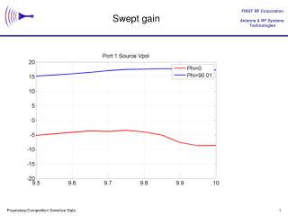
Results comparison of BEM against free wake for straight blade U=8 m/s tangential force dist. (Nt/m) normal force dist. (Nt/m) GAST - BEM axial induced velocity (m/s) GENUVP - free wake code
Results comparison of BEM against free wake for swept blade U=8 m/s, b=2 Increase of loading towards the tip Lower loads in more inboard sections normal force dist. (Nt/m) Increasing tip sweep tangential force dist. (Nt/m) GAST GENUVP
Results comparison of BEM against free wake for swept blade U=8 m/s, b=4 Similar behavior but larger effect for higher curvature BEM computations are expected to over predict power Increasing tip sweep GAST GENUVP
Results U=8m/s: Free-wake simulations Angle of attack distributions for swept blade • moderate tip offset (a=3) affects little the a.o.a except at the tip region • increasing “a” and “b” the complete blade is affected
Results comparison of BEM against free wake for swept blade – aerodynamic analysis results U=8 m/s Aerodynamic Power – % variation wrt straight blade BEM Free W power scaled for the same blade length
Results comparison of BEM against free wake for swept blade – aeroelastic analysis results GAST GENUVP U=8 m/s, b=2 GAST GENUVP U=8 m/s, b=4
Results comparison of BEM against free wake for swept blade – aeroelastic analysis results U=8 m/s Aerodynamic Power – % variation wrt straight blade BEM Free W power scaled for the same blade length
Blade sweep activates flapwise bending/torsion coupling Aft sweeping gives rise to nose down torsion deformation and potentially reduces flapwise loads Reduction in loads is accompanied by a reduction in power Comparing BEM based against free-wake aeroelastic simulations indicates that BEM models underestimate power loss. As expected BEM cannot properly account for the near wake induced effects driven by skewed shape of the tip of the blade Power loss increases with blade curvature (b parameter) and tip offset (a parameter) Conclusions
This work was partly funded by the European Commission under contract SES6 019945 (UpWind Integrated Project). Acknowledgements