Download
1 / 28
300 likes | 526 Views
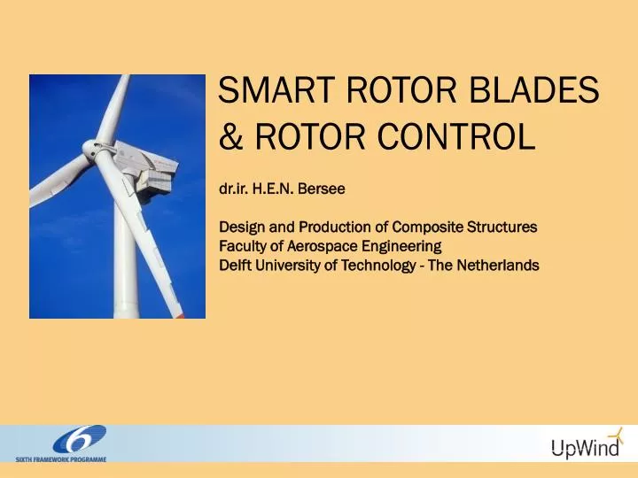
SMART ROTOR BLADES & ROTOR CONTROL. dr.ir. H.E.N. Bersee Design and Production of Composite Structures Faculty of Aerospace Engineering Delft University of Technology - The Netherlands. Introduction – Presentation Outline. Introduction What is a “Smart Rotor” UpWind work package 1B3

E N D
SMART ROTOR BLADES & ROTOR CONTROL dr.ir. H.E.N. Bersee Design and Production of Composite Structures Faculty of Aerospace Engineering Delft University of Technology - The Netherlands
Introduction – Presentation Outline • Introduction • What is a “Smart Rotor” • UpWind work package 1B3 • Aerodynamic devices • Concepts • Ongoing work • Adaptive aerofoils / Integrated Structures • Concepts • Ongoing work • Sensors and control • Conclusions
Introduction – Smart Rotor Blades • Work package 1B3: Smart Rotor Blade for Wind Turbines • Goal: • Controlling the blade’s loading through active control of the aerodynamics with spanwise distributed devices • Why? • With increasing rotor size for (future) off-shore turbines will cause more fatigue issues: • Mass effects • Increasing fluctuations in flow field • Logical solution: use the aerodynamics to control these fluctuations
Introduction – Smart Rotor Blades In order to be “Smart” one must sense, compute a reaction and react. For this accurate knowledge of the system (aerodynamics and structure) is needed. • So the issues/research areas are: • Aerodynamics • Structural integration/Actuators • Sensing • Control Moreover,a integrated solution is wanted.
Introduction – Smart Rotor Blades In other words • We want this control capability … … without compromising the robustness of current blade technology
Introduction – UpWind WP 1B3 • Work package 1B3: Smart Rotor Blade for Wind Turbines • Partners: • Risø National Laboratory (DK) • Energy research Centre of the Netherlands -ECN (NL) • University of Stuttgart (D) • LM Glasfiber A.S. (DK) • Fundación Robotiker (E) • VTT Technical Research Centre of Finland (SF) • Instytut Podstawowych Problemow Techniki -PAN (PL) • Institute of Physics, Academy of Sciences of the Czech Republic (CZ)
Aerodynamics • Requirements • Significant change in CL • Little aerodynamic delay (related to control) • Small power consumption (related to actuator possibilities)
Aerodynamics • Possibilities Options often inspired by helicopter rotor research: • Bend-twist coupling • Individual pitch control (full and partial span) • Trailing edge flaps • Camber control • Active blade twist • Micro tabs • Boundary layer control Many option are passive, too slow or require extremely large actuator power. Feasible candidates are…
Aerodynamics – state of the art • Trailing edge flaps and camber control At Risø: Model and experiments into aerofoils with (partially) deformable camber: For wind turbines aft part: continuous deformable trailing edge flaps (no hinges)
Aerodynamics – state of the art • Trailing edge flaps and camber control At Risø: Model and experiments into aerofoils with (partially) deformable camber: structural model Result: potential reduction in bending moment
Aerodynamics – state of the art • Trailing edge flaps and camber control At Risø: Model and experiments into aerofoils with (partially) deformable camber: result
Aerodynamics – state of the art • Trailing edge flaps and camber control At Risø: Model and experiments into aerofoils with (partially) deformable camber: 2D experiment • 2m blade section, 0.66m chord, 36 piezoelectric actuators as flaps (10% chord length). • Pitch +/- 1 deg. with and without (opposite) flap deflection • Reduction in change of lift 82%
Aerodynamics – state of the art • Trailing edge flaps and camber control At Risø: Model and experiments into aerofoils with (partially) deformable camber: 2D experiment
Aerodynamics -UpWind coproject • Trailing edge flaps and camber control At TU Delft: Experiments including structural dynamics and control • Blade with tailored dynamics • Fast pitch excitation to simulate the scaled dynamics of a full scale blade • Real time feedback controller designed with system identification • PZT based flexible flap • Experiments are on-going, results are possitive and being processed
Aerodynamics – state of the art Micro Tabs: By disturbing the boundary layer near the trailing edge… … the lift can be controlled
Aerodynamics – state of the art Micro Tabs: • Small (1-2%c), simple, lightweight, inexpensive • Fast response, easily controllable, small required movement • Great relative aerodynamic performance: it effectively changes sectional camber and modifies trailing edge flow (the Kutta condition)
Boundary layer control • Mainly used to reduce flow separation • Can achieve “virtual effective camber” control • Suction / Blowing • Synthetic Jets • Active Vortex Generators
Structural integration–state of the art • Simple design • Low maintenance requirements Integrated solution: Adaptive Materials Adaptive Structure: Embedding or externally applying materials that deform under a non-mechanical stimulus. • Advantages: • Lower weight • Lower maintenance
Structural integration–state of the art • Often mentioned adaptive materials: • Piezo electric materials. • Ionic polymers. • Electrostrictive materials. • Magnetostrictive materials. • Shape memory alloys. • Shape memory polymers. • Magneto-rheological fluids. But there are force, deformation and bandwidth requirements
Structural integration–state of the art • Force: Sufficient force must be exerted to deform the structure and to withstand aerodynamic loads • Deformation: The force must be applied over a certain range. • Bandwidth: The speed of the actuator must be high enough (at least 1-3Hz for the Smart Rotor). Suitable candidates: Piezo electrics (However, low strains: ~10-4) SMAs (However, low bandwidth: depends on cooling, hard to control)
Structural integration–state of the art • Piezo electrics: crystals that deform under an electric field • Often supplied in plates: high field through the thickness • Many ways of increasing deformation/deflection: • In benders • Using “3-3-effect” (stacks, active fiber composites) • Mechanical amplification
Structural integration–state of the art • SMAs: Temperature triggered phase transition causes recovery of certain amount of strain • Deforming at low T: material goes from twinned to detwinned martensite • Heating : materials transforms to austenite and recovers its original shape • Cooling : material returns to twinned martensite (unless restrained) without shape change • At high T: recovery is constantly “on”: pseudo elasticity
Structural integration • SMAs: Temperature triggered phase transition causes recovery of certain amount of strain • Bandwidth issues: • Cooling strategy • Use of the R-phase (low strains, but high rates because of higher and smaller temperature band) • Control: • Models of Academy of Sciences of the Czech Republic • Work on application and embedding
Example: SMA wire actuated trailing edge at VTT Structural integration–state of the art • SMAs: Temperature triggered phase transition causes recovery of certain amount of strain
Sensors and Control–state of the art • Sensoring: Robotiker • Possibilities for feedback: Measure for instance… • incoming flow field, • tip deflection / acceleration, • strain along the blade, especially at the root, Control: IPPT Threshold-based root bending alleviation through hinged blade root Control: TU Delft Feedback control on aerodynamic devices & actuator concepts
Conclusions • We’re aiming for an integrated solution where minimal actuation power (small devices) will result in a maximal effect (ΔCL) • Aerodynamic devices: most effective near trailing edge • Actuators: SMA or piezo based, either embedded (deformable surface), or as external actuator. • Current and future research into advanced aerodynamic and structural modeling, as well as control
Conclusions So in the future… Questions?
Conclusions So in the future… Questions?