Download
1 / 29
290 likes | 312 Views
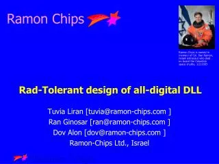
Rad-Hard Photomultiplier Chips™. Eric S. Harmon, Ph.D. Brad Cox, Ph.D. Vice President of Research Professor, Experimental High Energy Physics harmon@lightspintech.com +1 508-809-9052 Chris Neu . Ph.D. Asst. Prof. , Experimental High Energy Physics Jim Hyland, Ph.D

E N D
Rad-HardPhotomultiplier Chips™ Eric S. Harmon, Ph.D. Brad Cox, Ph.D. Vice President of Research Professor, Experimental High Energy Physics harmon@lightspintech.com +1 508-809-9052 Chris Neu. Ph.D. Asst. Prof. , Experimental High Energy Physics Jim Hyland, Ph.D David B. Salzman, Ph.DBob Hirosky, Ph.D. Assoc. Prof., Experimental High Energy Physics Brian Francis Mike Arenton, Ph.D. Sasha Ledovskoy, Ph.D.
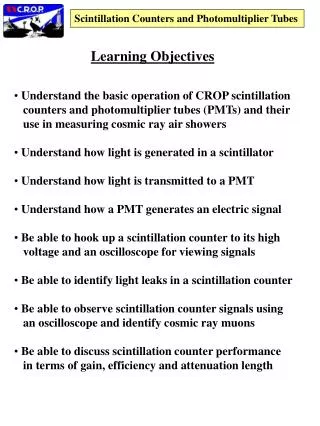
Outline • GaAs Photomultiplier ChipTM • Radiation damage in semiconductors • Bulk damage • Surface damage • Dark-count rate • Experimental Setup for GaAs PMC radiation testing • Next Steps • Summary
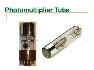
LightSpin’s GaAs Photomultiplier ChipTM • Array of single-photon avalanche devices (SPADs): • PMC™ uses GaAs (or GaInP) for direct absorption photonehp • SiPM and MPPCTM use Si for indirect photon+momentumehp • PMC™ 1 mm 1 mm prototypes in hand • Straightforward scaling • cm2 active area at high yield • Comparable production cost to SiPM
Cost? • High Volume silicon CMOS: $700 per 8” wafer = 2.5 ¢/mm2 (http://www.gsaglobal.org/email/2010/general/0222w.htm) • High Volume GaAs cost: $1,700 per 6” wafer = 10 ¢/mm2 • High Volume silicon = 100s of wafers per week! • High Volume GaAs = 10s of wafers per week! • Volume production wins • Ultimate cost of 1 cm2 detector (in high volume): • Silicon: $2.5 + packaging + testing • GaAs: $10 + packaging + testing • Current costs of SiPMs: $150/cm2 (http://sensl.com/estore/)
LightSpin Photomultiplier Chip™ • Designed, grew, fabbed, and tested 1 mm2 devices • 400 SPADs per mm2 • Extremely low dark current (10 pA/mm2) • High fill factor and high detection efficiency: • Single-photon detection efficiency > 20%
LightSpin Photomultiplier Chip™ • Designed, grew, fabbed, and tested 1 mm2 devices • 400 SPADs per mm2 • Extremely low dark current (10 pA/mm2) • High fill factor and high detection efficiency: • Single-photon detection efficiency > 20%
LightSpin GaAs PMC™ • Initial evaluation of radiation hardness mixed: • Devices not designed to be rad hard • Surface vs. bulk radiation damage • Packaging & test issues • Working on next generation: • 1st generation of Rad Hard GaAs PMC™ • Fab completion due this month • 2nd generation packaging
Radiation Damage NIEL Not directly useful for comparing materials
Relative lifetime damageGaAs vs. silicon variation in neutron damage arises from silicon NIEL curves • Generation Rate: G = ni V / • Radiation Damage: rad = 1/K • G() ≈ ni V K
Relative lifetime damageGaInP vs. silicon variation in neutron damage arises from silicon NIEL curves • Generation Rate: G = ni V / • ni(GaInP) ni(GaAs)/1E4
LightSpin preliminary investigation of 1 mm non rad hard GaAs PMC
Radiation Damage Analysis • For lowbias, observe reduction in dark current: • Radiation induced annealing? • Similar results reported by Sandia • Indicative of low “bulk” damage • For high bias, observe dramatic increase in dark current: • Surface damage (hopping conduction) • 1st generation Rad Hard GaAs PMC should not suffer this limitation
LightSpin – UVA collaboration • Test LightSpin GaAs PMC chips for Radiation Hardness: • Build new test box for GaAs PMC chips • Develop printed circuit board to allow testing of multiple devices while under irradiation • Test multiple devices: • Individual SPAD elements • PMC arrays (1.0 mm × 1.0 mm): • Approximately 100, 400, 1600 SPADs/mm2
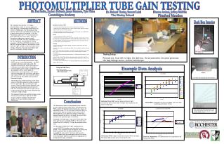
Test Setup New test fixture under construction DC bias supply (LED driver) Keithley 7001 switch box Keithley 237 SMU Programmable bias supply 20 BNC bias cables
1st generation PC Board Front of Board Back of Board BNC Bias Copper ground plane GaAs PMC SMA
2nd generation PC Board DIP Switch – Isolate individual devices Die attach area Bias connector Optional 50 termination Filtered bias to DUT 10 LIMO Connectors (100 Gohms to ground) RC bias filter
DC Current-Voltage non Rad Hard GaAs PMC Characteristics Board mounted device
DC Current-Voltage non Rad Hard GaAs PMC Characteristics Board mounted device Probed mounted device • Packaging + readout board introduced significant leakage current
Next Steps • 1st generation rad hard GaAs PMC: Nov. 2011 • 2nd generation PCB (improve dark current) • Improved Test Fixture • Radiation testing at PS at CERN • Made contact and discussed irradiations with facility managers.
Summary • Silicon APDs (including MAPD, SiPM and MPPC) will be unable to withstand the anticipated high-radiation environment of the endcap electromagnetic detector. Silicon devices also may not be able to be used in portions of the hadronic sections of the endcaps. • GaAs Photomultiplier Chips™ • Predicted to provide more than 100 times more radiation tolerance for neutrons • Predicted to provide 40 – 60 X times more radiation tolerance for protons/electrons • GaInP Photomultiplier Chips™ • Predicted to provide 1E6 times more radiation tolerance for neutrons • Predicted to provide 1E5 times more radiation tolerance for protons/electrons • LightSpin/UVA collaboration • Completing development of 2nd generation PMC Test Fixture: • Up to 10 devices can be tested during irradiation • DC and pulsed characterization • Ultra-low leakage design • 1st generation rad hard GaAs PMC & boards to UVA by end of year • Irradiation regime • EM • Hadronic • Hadronic + EM • control
Materials Limitations 100 10 Dark Noise (10 nsec window) 1 0.1
Irradiation materials limitations • Dark count rate & dark current modeled • Radiation damage factor K • Thermal generation rate G = ni V / • ni is the intrinsic carrier concentration • V = active volume • = lifetime (this is a function of the radiation damage, described by K) • Surface damage effects • Ultimate limits not included in calculation • Transmutation doping of active region • Tunneling • Extended defect generation (defect coalescence) • References: • Radiation Effects in Advanced Semiconductor Materials and Devices by C. Claeys and E. Simoen, Springer Series in Materials Science, 57, pp. 28 – 36, 132 – 138 (2002). • M. D. Osborne, P. R. Hobson, and S. J. Watts, “Numerical Simulation of Neutron Radiation Effects in Avalanche Photodiodes,” IEEE Trans. Electron. Dev. 47(3), pp. 529 – 536 (2000). • N. Dharmarasu et al., “High-radiation-resistant InGaP, InGaAs, and InGaAs solar cells for multijunction solar cells,“Appl. Phys. Lett. 79(15), pp. 2399 – 2401.
Radiation Damage • Bulk defects: intrinsic materials property, accurate measurements • Surface defects: depends on surface treatment: • Si: SiO2 vs. Si3N4 • GaAs: • Imperfect dielectric surface passivationvs. perfect single-crystal passivation X
Why is GaAs (GaInP) rad hard? • Generation Rate: G = ni V / • Radiation Damage: rad = 1/K • G() ≈ ni V K V = 1 mm 1 mm 1 µm
Why is GaAs (GaInP) rad hard? • Result for = 1E14/cm2 (SLHC Barrel max dose) • Cell density assumes saturation rate per cell occurs for count rates > 1E6 cps V = 1 mm 1 mm 1 µm
Why is GaAs (GaInP) rad hard? • Result for = 1E14/cm2 (SLHC Barrel max dose) V = 1 mm 1 mm 1 µm
Why is GaAs (GaInP) rad hard? • Result for = 7E15/cm2 (SLHC Barrel max dose) • Cell density assumes saturation rate per cell occurs for count rates > 1E6 cps V = 1 mm 1 mm 1 µm * 7.0e12 cps/mm2 = 1 µA/mm2 gain