Download
1 / 12
120 likes | 206 Views
Towards THz transistors *. Luis Jauregui. * Yu-Ming et al. Nano letters 2009, vol. 9, No 1, 422-426. Outline. THz what and why? RF CNT transistor model RF CNT transistors How do we improve the cutoff frequency? Experimental setup How can we improve them?. sub-mm-wave communications.

E N D
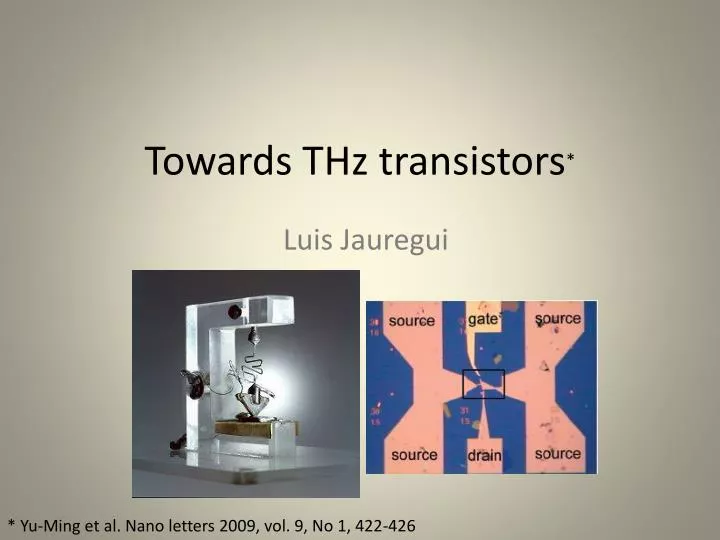
Towards THz transistors* Luis Jauregui * Yu-Ming et al. Nano letters 2009, vol. 9, No 1, 422-426
Outline • THz what and why? • RF CNT transistor model • RF CNT transistors • How do we improve the cutoff frequency? • Experimental setup • How can we improve them?.
sub-mm-wave communications 670-1000 GHz imaging systems THz what and why? • From 300 Ghz to 10+ Thz (1mm to 1um). • Rich spectral signature information(molecular resonances). • Faster electronics, compared to RF electronics, wider bandwidths. • Applications: • Security and defense, see through packages. • Medicine, Imaging cancer tumors, identification of drugs • Communications,
RF CNT transistor model • LM << LK , LK =16nH/µm • CT = CQ + CES , CQ = 100 aF/µm • CT= 50 aF/µm P. Burke, Solid-state electronics 48 (2004) 1981-1986
RF CNT transistors • Relevant frequency scales: • RC time; CNT length = 100nm, then C =4aF, R can be = 6.25KΩ • Transconductance 2.6GHz transistor P. Burke, Solid-state electronics 48 (2004) 1981-1986
How do we increase the cuttoff frequency? Increasing gm and decreasing Cgs P. Burke, Solid-state electronics 48 (2004) 1981-1986 What now? Theoretical limit for gm = 60μS *Guo et al., Performance projections for ballistic CNT field effect transistors, APL 2002; 60(17) : 3192-4
Experimental setup • Graphene by mechanical Exfoliation on • 300nm SiO2 on highly doped P type silicon. • Raman used to verify single layer. • Source and drain 1nm/50nm Ti, Pd. • Top Gate electrode 10nm/50nm Pd, Au. • 12nm Al2O3 by ALD at 250 C 20um Important: A functionalization layer of 50 cycles of NO2-TMA (trimethylaluminium) deposited first. To be able to deposit thin layer of alumina (12nm) without producing pinholes that cause gate leakage. Lg 500nm
DC Measurements Lg=360nm Conductance before and after depositing the top gate μ=400cm2/(V.s) Degradation probably due to the charged impurity scattering associated with the functionalization layer.
AC Measurements Lg=360nm They use the de-embedding procedure to calibrate the network analyzer using as short and open similar devices made on the same chip. • fT proportional to gm, meaning the graphene device is working as a transistor. • Cg~72fF, geometrically Cgs = 80fF.
AC Measurements Lg=150nm The measurement tool can not go to the cutoff frequency but they point out that extrapolating we reach a cutoff frequency of 26GHz.
How can we improve them? Increasing electron mobility or Vds and reducing gate length we can create faster transistors. Approaching ballistic transport in suspended graphene, Nature Nanotechnology, August 2008 By graphene nanoribbons?.