Download
1 / 42
420 likes | 581 Views
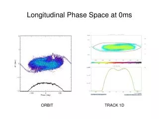
Phase Space Tomography. Bruno Muratori ASTeC - Daresbury Laboratory & Cockcroft Institute ERL07 Workshop, 23 rd May 2007. Introduction. Not only ERLs but … Phase space tomography measurements Emittance reconstruction & examples Online diagnostics & examples

E N D
Phase Space Tomography Bruno Muratori ASTeC - Daresbury Laboratory & Cockcroft Institute ERL07 Workshop, 23rd May 2007
Introduction • Not only ERLs but … • Phase space tomography measurements • Emittance reconstruction & examples • Online diagnostics & examples • Transverse deflecting cavities • Slice emittance measurements & examples • Energy spread measurements & examples • Examples: 4GLS, XFEL, FLASH, PITZ2, … • Low energy measurements ? • Space charge ‘compensation’ ? • → Changes to matching requirements
Projected Transverse Emittance • Requirements / Constraints: • Overall strength of quadrupoles (not too high to avoid chromaticity & non-linear effects) • Length of FODO lattice (space / cost) • Sensitivity to mismatch & alignment errors • Space charge • Phase advance / FODO Cell (usually 45°, also 20°, 22.5°, 60°, 67.5° & 90° considered) • Done offline ? → cannot monitor beam all the time, only done during set-up & studies • Precise, even if phase advance not 45° (FLASH)
Slice Emittance Measurements • Kicker used to select single bunch out of (e.g. 1 MHz) bunch train • Deflecting cavity pulsed (1 microsecond only) streaks selected bunch • Resolution should be unstreaked spot size / maximum streak rate
Slice Emittance Measurements • Kicker – deflects the bunch horizontally (FLASH) • Use a RF cavity operated in a transverse deflecting mode, operating at zero RF phase-crossing to “streak” the beam -> LoLA (Loew, Larsen, Altenmueller ~1963) • LoLA cavity streaks transversally & in one plane only as modes locked – (e.g. vertically @ FLASH) • First OTR at about 90° phase advance (should be ?) • Depends how many screens are used … • Translates temporal profile into transverse profile • High resolution ~ 10 fs (20 fs FWHM bunch length measured so far)
V ( t ) V ( t ) á D ñ á D ñ y y s s y y p 2 - - e e s 2 . 4 4 m s 2 . 4 4 m z z TM D y » D y » 6 0 ° 6 0 ° 11 b b b b c p c p LoLA Cavity • Travelling wave transverse RF deflecting cavity • Gives kick in one direction only (x or y) • Kick with z dep. → head kicked more than tail • High frequency (2856 MHz) & length (2.44 m or 3.64 m) & operated @ 45°C
LoLA Cavity • Transverse position on screen is • Transfer Matrix to screen gives βd – deflector, βs – screen • Want R12 big → sinΔψ = 1, βs small → make βd large • Beam size on the screen
Slice Emittance Measurements @ FLASH • R matrix from LoLA to screen known • Only need width at screen → slice emittance • Bunch length given knowledge of kick
XFEL • Projected emittance measurements • Bunch length measurements • Slice emittance and energy spread measurements • Complete non-disruptive online monitoring – Special Diagnostics (SD) requires as many successive bunches as there are screens • Cannot be done with quad-scan method • Take into account: • Space charge effects • Chromaticity • Alignment errors • Statistical errors
OTR (x,y) OTR (x,y) OTR (x,y) KICKER z Online Transverse Diagnostics • Can be used continuously in FODO lattice diagnostic • Always know main bunch properties • Important to predict performance & protect FEL • Synchrotron radiation from kick ? • Not an issue at FLASH
Fixing the Phase Advance • Normal Twiss transformation formula (0 to 1) • β and α the same • For ‘OFODO’ lattice: Lq= ± [2(1 – cosΔμ)]1/2 • Min / max Lq → smallest / largest phase advance μ, L – drift length, q = LQUADk (k – quad strength) • Small μ → increased sensitivity to alignment/errors • Small k → increased sensitivity to space charge • Large k → increased sensitivity to chromaticity
βx,y, βy βx z TDC (x) TDC (y) OTR (x,y) OTR (x,y) OTR (x,y) OTR (x,y) Fixing the Phase Advance (4GLS) • Lq determined →β,α determined & spot size fixed ! • Two LoLA cavities (x & y planes) • 3 OFODO cells, 4GLS → 45° phase advance each or ? ~2 m
Energy Spread Measurements (FLASH) • Both bunch compressors off • All cavities in modules on-crest (for minimum energy spread) • LoLA cavity to streak beam • Go through dipole • OTR after first collimator dogleg dipole • Two bunches in the collimator at OTR shown • One streaked with LoLA the other not streaked • → Energy Spread Measurement
Energy Spread Measurements @ FLASH Energy Head Unstreaked bunch Tail Time
Low Energies (PITZ2) ? • Charge: 1 nC • Energies considered:6.6 (no booster) to 50 MeV • Tracked with ASTRA inside diagnostics section both with and without space charge • Main questions / concerns remaining: • Do we adjust for space charge effects ? • How do we interpret results ?
Matching into Diagnostic @ 32 MeV • Different match for each energy considered • Space left for LoLA-type deflecting cavity
Tomography Section β Functions • Link between quad strength & FODO length • Quadrupole length 0.06 m • Quadrupole strength 4.7 T/m @ 32 MeV
Tomography Section Phase Advance • Phase advance per FODO cell is 45° • 4 OTR screens • Beam size ~ 0.1mm in both planes
Beam Size (x) @ 32 MeV • Space charge has no big effect @ 32 MeV • Emittance growth negligible (y plane similar) • No compensation required
Beam Size (x) @ 14.5 MeV • Space charge has very big effect • Emittance growth appreciable (no s.c. history !)
Beam Size (y) @ 14.5 MeV • Quadrupole strength @ 14.5 MeV: 2.28 T/m • Emittance (proj. trans.) grows by ~ 0.5 %
Beam Size (x) @ 14.5 MeV • Quad strength increased to 2.43 T/m • Is this necessary ?
Beam Size (y) @ 14.5 MeV • Only linear space charge compensated • x plane vs. y plane asymmetry
Space Charge Compensation Problems • Increasing quadrupole strength → incompatibility with initial Twiss parameters • For ‘OFODO’ lattice: Lq= ± [2(1 – cosΔμ)]1/2 • Min / max Lq → smallest / largest phase advance μ, L – drift length, q = LQUADk (k – quad strength) • Small μ → increased sensitivity to alignment/errors • Small k → increased sensitivity to space charge • Large k → increased sensitivity to chromaticity • Lq determined →β,α determined & spot size fixed ! • Therefore system cannot be matched … • Should design tomography line with different initial Twiss parameters at start • Use GPT (General Particle Tracer) or similar (?) program which includes space charge …
Conclusion • Very accurate method • Transverse diagnostics (online ?) • Bunch length & slice emittance with TDC • Useful at low energies (PITZ2) ? • Space charge compensation • EO measurements better ? • Best phase advance / OFODO cell ? • Space charge • Chromaticity • Alignment errors • Statistical errors • Thank you for your time !
Beam Matrix σ • (x x’)σ-1(x x’)T = 1 = • -> σ2,2x2 - 2σ1,2xx’ + σ1,1x’2 = det(σ)
Emittance Determination • Transformation from 0 to i • For 3 screens this becomes so
Emittance Determination • So the projected transverse emittance is • From which we deduce the Twiss parameters • Can do a tomography reconstruction of phase space