Download
1 / 24
240 likes | 242 Views
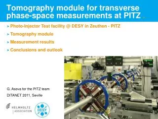
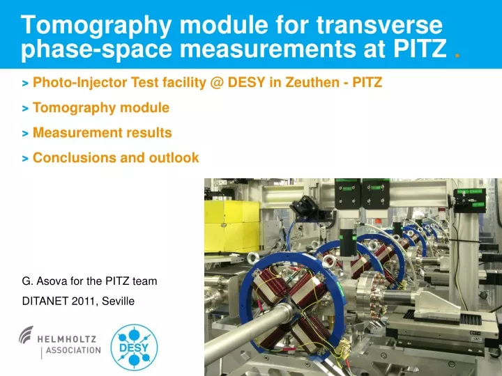
Tomography module for transverse phase-space measurements at PITZ. Photo-Injector Test facility @ DESY in Zeuthen - PITZ Tomography module Measurement results Conclusions and outlook. G. Asova for the PITZ team DITANET 2011, Seville. 1½ cell RF gun cavity 1.3 GHz. Cs 2 Te photocathode.

E N D
Tomography module for transverse phase-space measurements at PITZ . • Photo-Injector Test facility @ DESY in Zeuthen - PITZ • Tomography module • Measurement results • Conclusions and outlook G. Asova for the PITZ team DITANET 2011, Seville
1½ cell RF gun cavity 1.3 GHz Cs2Tephotocathode laser beam Bucking solenoid e- beam Main solenoid Photo-Injector Test facility Produce electron beams with minimized transverse emittanceas required for the European XFEL photo-injector: < 1 mm mrad for 1 nC 6.7 MeV/c 25 MeV/c transverse projected emittance
0.1 nC, 14 laser pulses 1 nC, 6 laser pulses Phase-space portraits • Standard measurement method – slit scan • Separately scan the two transverse planes • Sensitive to signal-to-noise ratio → multi-shot measurements to collect as full as possible signal → smearing of the phase space due to possible machine fluctuations
Tomography Reconstruction of an object from a number of its projections at different angles - Radon transform
Phase-space tomographic reconstruction bx e- by (focusing – drift – defocusing – drift) FODO cell • equidistant angular steps between the screens for both planes (2D) • the beam parameters at the entrance of the lattice are adjusted
e- Tomography module • Design for 15-30 MeV/c, 1 nC • Challenging matching due to space-charge impact • Slow and complicated analysis
Major components x 5 FODO cells Components (details in poster): • Quadrupole magnets in FODO cells • Screen stations • Steering magnets • BPMs Short cells: • Short quadrupoles Leff = 43 mm • Strong focusing • Precise alignment along the full FODO lattice • 20 mrad quadrupole angular misalignment • 100 mm longitudinal misplacement
Measurements with the setup • Nominal charge of 1 nC • Emittance evolution along the beamline - cross-check the calculated emittance versus results from slit scans • Different charge densities at the photo-cathode • Reproducibility of the measurements • Lower charges ≥ 100 pC • Common machine setup: • Max power from gun and booster, phases for max mean momentum gain, ~ 25 MeV/c • Laser temporal profile – flat top with 2/22\2 ps
6 bunches in the train Slit scans, z = 5.74 m Orthogonal! 1 bunch in the train TOMO, z = 13.04 m Strong tails Substructure Measured phase spaces, 1 nC
Beam profile along the beamline 1 nC EMSY3 TOMOGRAPHY EMSY1 measuredsxy measuredsy measuredsx simulatedsxy
EMSY3 Dex, y ~ 30% TOMO EMSY1 Emittance evolution along the beamline 1 nC
bx by Matching for 1 nC, 25 MeV/c • Hard to keep both planes periodic along the FODO lattice • by matched very good, but not bx • consistent for different laser spot sizes, solenoid current, quadrupole settings, bunch charges Dby < 20% - for such mismatchesasolution can always be found
bx by 392 A 396 A 398 A 100 pC X-plane • Emittance decreases with the solenoid focusing • the orientation of the three distributions is the same – matching worked in these cases • As the area of the phase space decreases, the substructure comes closer to the main beam for higher solenoid currents
Conclusions & outlook • Tomography module successfully commissioned • Results cross-checked with standard for PITZ slit scans • Details on the phase spaces downstream the beamline reconstructed in great details for short bunch trains • The two transverse planes resolved simultaneously • Kicker magnets to be installed for measurements ofselected bunch in the train • Transverse deflecting cavity for longitudinal phase-spacemeasurements
The PITZ collaboration Colleagues participating in measurements / new design: • DESY, Zeuthen site:J. Bähr, H.J. Grabosch, M. Gross, A, Donat, I. Isaev*, Y. Ivanisenko**, G. Kourkafas***, G. Klemz, D. Malyutin, M. Krasilnikov, M. Mahgoub, J. Meissner, A. Oppelt, M. Otevrel, B. Petrosyan, S. Rimjaem, A. Shapovalov*, F. Stephan, G. Vashchenko • DESY, Hamburg site:A. Brinkmann, K. Flöttmann, S. Lederer, D. Reschke, S. Schreiber • BESSY Berlin:R. Ovsyannikov, D. Richter, A. Vollmer • ASTeC STFC Daresbury Lab:B. Militsyn • INRNE Sofia:G. Asova, I. Bonev, I. Tsakov • INR Troitsk:A.N. Naboka, V. Paramonov, A.K. Skassyrskaia, A. Zavadtsev • LAL Orsay:M. Jore, A. Variola • LASA Milano:P. Michelato, L. Monaco, D. Sertore • MBI Berlin:I. Will • TU Darmstadt:S. Franke, W. Müller • Uni Hamburg:J. Rönsch-Schulenburg • YERPHI Yerevan:L. Hakobyan, M. Khojoyan * on leave from NRNU, Moscow, Russia ** on leave from IERT, NAS, Kharkiv, Ukraine *** on leave from Athens, Greece R. Brinkmann, U. Gensch, J. Knobloch, L. Kravchuk, V. Nikoghosyan, C. Pagani, L. Palumbo, J. Rossbach, W. Sandner, S. Smith, T. Weiland, G. Wormser
Applicability of different algorithms to limited data sets Tomographic reconstruction • N rotations → N projections of the (x, y) • Which algorithms are applicable to small N? → N = 4 Backprojection Filtered backprojection Algebraic reconstruction Maximum entropy @ UMER, PITZ? @ FLASH, PITZ
Reconstruction of 1 nC, intensity cut 0.5 % intensity cut Slit scan Tomography ex, N = 1.07 mm mrad ex, N = 1.3 mm mrad The contribution of the low-intensity bins is negligible.
Reconstruction of 1 nC, intensity cut 5 % intensity cut Slit scan Tomography ex, N = 1.06 mm mrad ex, N = 1.07 mm mrad • Common features in both distributions • elongated non-symmetric tails • non-symmetric density of the core
PITZ Produce electron beams with minimized transverse projected emittance as required for the European XFEL, < 1 mm mrad Cs2Te cathode booster RF gun + solenoids transverse projected emittance Beam momentum ~ 6.7 MeV/c /25 MeV/c Nominal bunch charge 1 nC
FODO cell (focusing – drift – defocusing – drift) Emittance measurements at PITZ Phase-space tomographic reconstruction e- beam • equidistant angular steps between the screens for both planes (2D) • rms spot size is uncharged • the beam parameters at the entrance of the lattice are adjusted • the data treatment assumeslinear transport between the screens
Screen stations • Actuator holding Ce:YAG-doped and OTR screens • Precisely movable actuator • 2 different actuator designs Nominal Test, 2 optical systems • Design momentum for high charge densities (30 MeV/c, 1 nC) • Small beam dimensions (0.125 mm for 30 MeV/c) • Minimize multiple scattering within the Si layer 100 mm thickness
Optical system Movable mirror to compensate the different path length for YAG/OTR screen M = 0.21, resolution about 45 um M = 0.13, to adjust the beam orbit Pipe to mitigate stray light 16-bit monochromatic CCD camera
Transverse phase-space measurements at PITZ Single slit scan – standard measurement procedure * Values obtained from solenoid scans for various laser spot sizes. • Improved RF gun stability • Improved laser stability and beam transport • Replaced magnetizable components → critical at low energies