Download
1 / 24
240 likes | 253 Views
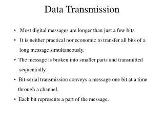
Chapter 6. Baseband Data Transmission. 6.4 Raised-Cosine Pulse Spectrum. To ensure physical realizability of the overall pulse spectrum P(f) , the modified P(f) decreases toward zero gradually rather than abruptly

E N D
6.4 Raised-Cosine Pulse Spectrum • To ensure physical realizability of the overall pulse spectrum P(f), the modified P(f) decreases toward zero gradually rather than abruptly • Flat portion, which occupies the frequency band 0≤|f| ≤f1 for some parameter f1 to be defined • Roll-off portion, which occupies the frequency band f1≤|f| ≤2B0-f1 • One full cycle of the cosine function defined in the frequency domain, which is raised up by an amount equal to its amplitude • The raised-cosine pulse spectrum
The roll-off factor • The amount of intersymbol interference resulting from a timing error ∆t decreases as the roll-off factor is increased form zero to unity. • For special case of α=1
Transmission-Bandwidth Requirement • The transmission bandwidth required by using the raised-cosine pulse spectrum is • Excess channel • The transmission bandwidth requirement of the raised-cosine spectrum exceeds that of the optimum Nyquist channel • When the roll-off factor is zero, the excess bandwidth is reduced to zero • When the roll-off factor is unity, the excess bandwidth is increased to B0.
Two additional Properties of the Raised-Cosine Pulse Spectrum • Property 1 • The roll-off protion of the spectrum P(f) exhibits odd symmetry about the midpoints f=±B0 • A unique characterization of the roll-off portion of the raised-cosine spectrum
Fig. 3.24(a) and 6.4(a), they are basically of an identical mathematical form, except for two minor differences : • The baseband raised-cosine pulse spectrum P(f) of Fig. 6.4(a) is centered on the origin at f=0, whereas the vestigial sideband spectrum of Fig. 3.24(a) is centered on the sinusoidal carrier frequency fc • The parameter fv in Fig. 6.4(a) refers to the excess bandwidth measured with respect to the ideal brick-wall solution for zero intersymbol interference, whereas the parameter fv in Fig. 3.24(a) refers to the excess bandwidth measured with respect to the optimum bandwidth attainable with single sideband modulation..
Property 2 • The finite summation of replicas of the raised-cosine pulse spectrum, spaced by 2B0 hertz, equals a constant • Sampling the modified pulse response p(t) at the rate 1/2B0,
Finally, nothing that the Fourier transform of the delta function is unity, Eq. (6.29) is merely another way of describing the desired form shown in Eq. (6.27) • Given the modified pulse shape p(t) for transmitting data over an imperfect channel using discrete pulse-amplitude modulation at the data rate 1/T, the pulse shape p(t) eliminates intersymbol interference if, and only if, its spectrum P(f) satisfies the condition
Root Raised-Cosine Pulse Spectrum • A more sophisticated form of pulse shaping for baseband digital data transmission is to use the root raised-cosine pulse spectrum • The pulse shaping is partitioned equally between two entities • The combination of transmit-filter and channel constitutes one entity. With H(f) known and P(f) defined by Eq. (6.17) for a prescribed roll-off factor, we may use Eq. (6.31) to determine the frequency response of the transmit filter. • The receive filter constitutes the other entity. Hence, for the same roll-off factor we may use Eqs. (6.17) and (6.32) to determine the frequency response of the receive-filter.
6.5 Baseband Transmission of M-ary Data • The output of the line encoder takes on one of M possible amplitude levels with M>2. • Signaling rate (symbol rate) • 1/T • Symbols per second, bauds • The symbol duration T of the M-ary PAM system is related to the bit duration Tb of a binary PAM system
6.6 The Eye Pattern • Eye Pattern • Be produced by the synchronized superposition of successive symbol intervals of the distorted waveform appearing at the output of the receive-filter prior to thresholding • From an experimental perspective, the eye pattern offers two compelling virtues • The simplicity of generation • The provision of a great deal of insightful information about the characteristics of the data transmission system, hence its wide use as a visual indicator of how well or poorly a data transmission system performs the task of transporting a data sequence across a physical channel.
Timing Features • Three timing features pertaining to binary data transmission system, • Optimum sampling time : The width of the eye opening defines the time interval over the distorted binary waveform appearing at the output of the receive-filter • Zero-crossing jitter : in the receive-filter output, there will always be irregularities in the zero-crossings, which, give rise to jitter and therefore non-optimum sampling times • Timing sensitivity : This sensitivity is determined by the rate at which the eye pattern is closed as the sampling time is varied.
The Peak Distortion for Intersymbol Interference • In the absence of channel noise, the eye opening assumes two extreme values • An eye opening of unity, which corresponds to zero intersymbol interference • An eye opening of zero, which corresponds to a completely closed eye pattern; this second extreme case occurs when the effect of intersymbol interference is severe enough for some upper traces in the eye pattern to cross with its lower traces.
Noise margin • In a noisy environment, • The extent of eye opening at the optimum sampling time provides a measure of the operating margin over additive channel noise • Eye opening • Plays an important role in assessing system performance • Specifies the smallest possible noise margin • Zero peak distortion , which occurs when the eye opening is unity • Unity peak distortion, which occurs when the eye pattern is completely closed. • The idealized signal component of the receive-filter output is defined by the first term in Eq. (6.10) • The intersymbol interference is defined by the second term
Eye pattern for M-ary Transmission • M-ary data transmission system uses M encoded symbols • The eye pattern for an M-ary data transmission system contains (M-1) eye openings stacked vertically one on top of the other. • It is often possible to find asymmetries in the eye pattern of an M-ary data-transmission system, which are caused by nonlinearities in the communication channel or other parts of the system.
6.9 Summary and Discussion • Baseband data transmission, for which the channel is of a low-pass type • Band-pass data transmission, for which the channel is of a band-pass type • The intersymbol interference problem, which arises due to imperfections in the frequency response of the channel • ISI refers to the effect on that pulse due to cross-talk or spillover from all other signal pulses in the data stream applied to the channel input • A corrective measure widely used in practice is to shape the overall pulse spectrum of the baseband system, starting from the source of the message signal all the way to the receiver. • The eye pattern portrays the degrading effects of timing jitter, ISI, channel noise • ISI is a signal-dependent phenomenon, it therefore disappears when the information-bearing signal is switched off. • Noise is always there, regardless of whether there is data transmission or not. • Another corrective measure for dealing with the ISI; channel equalization