Download
1 / 56
570 likes | 890 Views
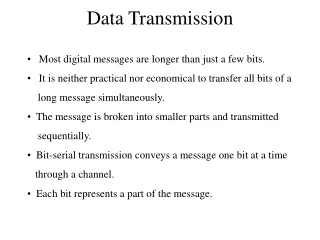
BASEBAND DATA TRANSMISSION. by Dr. Uri Mahlab. Communication system. Transmitter. Receiver. Information source. Channel. Decision. Block diagram of an Binary/M-ary signaling scheme. Timing. H T (f). (X T (t. H c (f). (X(t. Information source. Pulse generator. Trans filter.

E N D
BASEBAND DATA TRANSMISSION by Dr. Uri Mahlab Dr. Uri Mahlab
Communication system Transmitter Receiver Information source Channel Decision Dr. Uri Mahlab
Block diagram of an Binary/M-ary signaling scheme Timing HT(f) (XT(t Hc(f) (X(t Information source Pulse generator Trans filter channel + Channel noise n(t) + Y(t) A/D Receiver filter Output HR(f) Clock recovery network Dr. Uri Mahlab
Block diagram Description {dk}={1,1,1,1,0,0,1,1,0,0,0,1,1,1} Tb Tb Timing HT(f) (X(t (XT(t Information source Pulse generator Trans filter For bk=1 Tb For bk=0 Tb Dr. Uri Mahlab
Block diagram Description (Continue - 1) {dk}={1,1,1,1,0,0,1,1,0,0,0,1,1,1} Tb Timing HT(f) (X(t (XT(t Information source Pulse generator Trans filter For bk=1 Tb Tb Transmitter filter For bk=0 Tb Tb Dr. Uri Mahlab
Block diagram Description (Continue - 2) {dk}={1,1,1,1,0,0,1,1,0,0,0,1,1,1} Tb Timing HT(f) (X(t (XT(t Information source Pulse generator Trans filter 100110 Tb 2Tb 5Tb 6Tb t 3Tb 4Tb Dr. Uri Mahlab
Block diagram Description (Continue - 3) {dk}={1,1,1,1,0,0,1,1,0,0,0,1,1,1} Tb Timing HT(f) (X(t (XT(t Information source Pulse generator Trans filter 100110 Tb 2Tb 5Tb 6Tb t 3Tb 4Tb Tb 2Tb 5Tb 6Tb t 3Tb 4Tb Dr. Uri Mahlab
Block diagram Description (Continue - 4) Timing HT(f) HR(f) (X(t Information source Pulse generator Trans filter + Receiver filter Channel noise n(t) Tb 2Tb 5Tb 6Tb t 3Tb 4Tb Tb 2Tb 5Tb 6Tb t 3Tb 4Tb t Dr. Uri Mahlab
Block diagram Description (Continue - 5) Tb 2Tb 5Tb 6Tb t 3Tb 4Tb Tb 2Tb 5Tb 6Tb t 3Tb 4Tb t Dr. Uri Mahlab
Block diagram of an Binary/M-ary signaling scheme Timing HT(f) (Xt(T Hc(f) (X(T Information source Pulse generator Trans filter channel + Channel noise n(t) + Y(t) Receiver filter A/D Output HR(f) Clock recovery network Dr. Uri Mahlab
Block diagram Description Tb 2Tb 5Tb 6Tb t 3Tb 4Tb Tb 2Tb 5Tb 6Tb t 3Tb 4Tb t t 1 0 0 0 1 0 1 0 0 1 1 0 Dr. Uri Mahlab
Block diagram of an Binary/M-ary signaling scheme Timing HT(f) (XT(t Hc(f) (X(t Information source Pulse generator Trans filter channel + Channel noise n(t) + Y(t) A/D Receiver filter Output HR(f) Clock recovery network Dr. Uri Mahlab
Explanation of Pr(t) HT(f) Hc(f) HR(f) Pg(t) Pr(t) Trans filter channel Receiver filter HT(f) Hc(f) HR(f) Pg(f) Pr(f) Dr. Uri Mahlab
Analysis and Design of Binary Signal The output of the pulse generator X(t),is given by Pg(t) is the basic pulse whose amplitude ak depends on .the kth input bit Dr. Uri Mahlab
The input to the A/D converter is For tm =mTb+td and td is the total time delay in the system, we get. t t t2 t3 t tm t1 Dr. Uri Mahlab
The output of the A/D converter at the sampling time tm =mTb+td Tb 2Tb 5Tb 6Tb t 3Tb 4Tb t2 t3 t tm t1 Dr. Uri Mahlab
ISI - Inter Symbol Interference t2 t3 t tm t1 Dr. Uri Mahlab
Explanation of ISI HT(f) Hc(f) HR(f) Pg(t) Pr(t) Trans filter channel Receiver filter t t BandPass Filter Fourier Transform Fourier Transform f f HT(f) Hc(f) HR(f) Pr(f) Pg(f) Trans filter channel Receiver filter Dr. Uri Mahlab
Explanation of ISI - Continue t t BandPass Filter Fourier Transform Fourier Transform f f Tb 2Tb 5Tb 6Tb t 3Tb 4Tb Dr. Uri Mahlab
-The pulse generator output is a pulse waveform If kth input bit is 1 if kth input bit is 0 -The A/D converter input Y(t) Dr. Uri Mahlab
5.2 BASEBAND BINARY PAM SYSTEMS - minimize the combined effects of inter symbol interference and noise in order to achieve minimum probability of error for given data rate. Dr. Uri Mahlab
5.2.1Baseband pulse shaping The ISI can be eliminated by proper choice of received pulse shape pr (t). Doe’s not Uniquely Specify Pr(t) for all values of t. Dr. Uri Mahlab
To meet the constraint, Fourier Transform Pr(f) of Pr(t), should satisfy a simple condition given by the following theorem Theorem Proof Dr. Uri Mahlab
Which verify that the Pr(t) with a transform Pr(f) Satisfy ZERO ISI Dr. Uri Mahlab
The condition for removal of ISI given in the theorem is called Nyquist (Pulse Shaping) Criterion 1 -2Tb -Tb Tb 2Tb Dr. Uri Mahlab
Pg(f) HT(f) Hc(f) HR(f) Pr(f) The Theorem gives a condition for the removal of ISI using a Pr(f) with a bandwidth larger then rb/2/. ISI can’t be removed if the bandwidth of Pr(f) is less then rb/2. Tb 2Tb 5Tb 6Tb t 3Tb 4Tb Dr. Uri Mahlab
Particular choice of Pr(t) for a given application The smallest values near Tb, 2Tb, … In such that timing error (Jitter) will not Cause large ISI Shape of Pr(f) determines the ease with which shaping filters can be realized. Dr. Uri Mahlab
A Pr(f) with a smooth roll - off characteristics is preferable over one with arbitrarily sharp cut off characteristics. Pr(f) Pr(f) Dr. Uri Mahlab
In practical systems where the bandwidth available for transmitting data at a rate of rb bits\sec is between rb\2 to rb Hz, a class of pr(t) with a raised cosine frequency characteristicis most commonly used. A raise Cosine Frequency spectrum consist of a flat amplitude portion and a roll off portion that has a sinusoidal form. Dr. Uri Mahlab
raised cosine frequency characteristic Dr. Uri Mahlab
Summary The BW occupied by the pulse spectrum is B=rb/2+b. The minimum value of B is rb/2 and the maximum value is rb. Larger values ofbimply that morebandwidth is required for a given bit rate, however it lead for faster decaying pulses, which means that synchronization will be less critical and will not cause large ISI. b =rb/2 leads to a pulse shape with two convenient properties. The half amplitude pulse width is equal to Tb, and there are zero crossings at t=3/2Tb, 5/2Tb…. In addition to the zero crossing at Tb, 2Tb, 3Tb,…... Dr. Uri Mahlab
5.2.2 Optimum transmitting and receiving filters The transmitting and receiving filters are chosen to provide a proper Dr. Uri Mahlab
-One of design constraints that we have for selecting the filters is the relationship between the Fourier transform of pr(t) and pg(t). Where td, is the time delay Kc normalizing constant. In order to design optimum filter Ht(f) & Hr(f), we will assume that Pr(f), Hc(f) and Pg(f) are known. Portion of a baseband PAM system Dr. Uri Mahlab
Pg(f) HT(f) Hc(f) HR(f) Pr(f) If we choose Pr(t) {Pr(f)} to produce Zero ISI we are left only to be concerned with noise immunity, that is will choose Dr. Uri Mahlab
Noise Immunity Problem definition: • For a given : • Data Rate - rb • Transmission power - ST • Noise power Spectral Density - Gn(f) • Channel transfer function - Hc(f) • Raised cosine pulse - Pr(f) Choose Dr. Uri Mahlab
Error probability Calculations At the m-th sampling time the input to the A/D is: We decide: Dr. Uri Mahlab
A=aKc The noise is assumed to be zero mean Gaussian at the receiver input then the output should also be Zero mean Gaussian with variance No given by: Dr. Uri Mahlab
y(tm) 0 A b Dr. Uri Mahlab
y(tm) -A A y(tm) 0 Dr. Uri Mahlab
y(tm) -A A VTransmit Vreceived Dr. Uri Mahlab
Q(u) dz= U Dr. Uri Mahlab
Perror decreases as increase Hence we need to maximize the signal to noise Ratio Thus for maximum noise immunity the filter transfer functions HT(f) and HR(f) must be xhosen to maximize the SNR Dr. Uri Mahlab
Optimum filters design calculations We will express the SNR in terms of HT(f) and HR(f) We will start with the signal: The psd of the transmitted signal is given by:: Dr. Uri Mahlab
And the average transmitted power ST is The average output noise power of n0(t) is given by: Dr. Uri Mahlab
The SNR we need to maximize is Or we need to minimize Dr. Uri Mahlab
Using Schwartz’s inequality The minimum of the left side equaity is reached when V(f)=const*W(f) If we choose : Dr. Uri Mahlab
The filter should have alinear phase response in a total time delay of td Dr. Uri Mahlab
Finally we obtain the maximum value of the SNR to be: Dr. Uri Mahlab