Download
1 / 36
360 likes | 425 Views
Chapter 6 : Metallic Transmission Lines Chapter contents. 6.1 Introduction 6.2 Metallic Transmission Lines 6.2.1 Parallel-Conductor Transmission Lines 6.2.2 Coaxial (Concentric) Transmission Line 6.3 Metallic Transmission Line Equivalent Circuit 6.3.1 Uniformly distributed transmission line

E N D
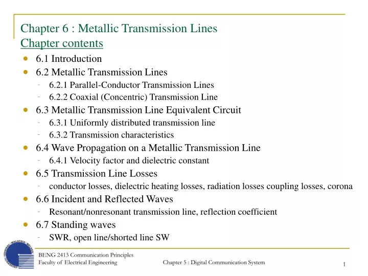
Chapter 6 : Metallic Transmission LinesChapter contents • 6.1 Introduction • 6.2 Metallic Transmission Lines • 6.2.1 Parallel-Conductor Transmission Lines • 6.2.2 Coaxial (Concentric) Transmission Line • 6.3 Metallic Transmission Line Equivalent Circuit • 6.3.1 Uniformly distributed transmission line • 6.3.2 Transmission characteristics • 6.4 Wave Propagation on a Metallic Transmission Line • 6.4.1 Velocity factor and dielectric constant • 6.5 Transmission Line Losses • conductor losses, dielectric heating losses, radiation losses coupling losses, corona • 6.6 Incident and Reflected Waves • Resonant/nonresonant transmission line, reflection coefficient • 6.7 Standing waves • SWR, open line/shorted line SW BENG 2413 Communication Principles Faculty of Electrical Engineering
6.3 Metallic Transmission Line Equivalent Circuit6.3.1 Uniformly Distributed Transmission Lines • characteristics of a transmission line are determine by : • Electrical properties – wire conductivity, insulator dielectric constant • Physical properties – wire diameter, conductor spacing • the above properties determine the primary electrical constant of the transmission line : • series DC resistance (R) : occurs along the line • series inductance (L) : occurs along the line • shunt capacitance (C) : occurs between the conductors • shunt conductance (G) : occurs between the conductors • these primary constants are uniformly distributed throughout the length of the line and commonly called as distributed parameters. • to simplify analysis, distributed parameters are normally given in unit length of cable to form an artificial model of a line – lump parameters (e.g. ohm per meter). BENG 2413 Communication Principles Faculty of Electrical Engineering
6.3.1 Uniformly Distributed Transmission Lines • electrical equivalent circuit for a metallic two-wire parallel transmission line showing the relative placement of the various lumped parameters : BENG 2413 Communication Principles Faculty of Electrical Engineering
6.3.2 Transmission Characteristics • transmission characteristics of a transmission line are called secondary constants and are determined from the previous four primary constants. • the secondary constants are : • characteristic impedance • propagation constant 6.3.2.1 Characteristic impedance • for a maximum power transfer from the source to the load (i.e. no reflected power), a transmission line must be terminated in a purely resistive load equal to the characteristic impedance of the transmission line. • characteristic impedance (Z0) is defined as the impedance seen looking into an infinitely long line or the impedance seen looking into a finite length of line that is terminated in a purely resistive load with a resistance equal to the characteristic impedance of the line. BENG 2413 Communication Principles Faculty of Electrical Engineering
6.3.2.1 Characteristic Impedance • an infinitely long line can be simulated if a finite line is terminated in a purely resistive load equal to Z0, where all the energy that enters the line from the source is dissipated in the load (totally lossless line). • Below figure shows a single section of a transmission line terminated in load ZL equal to Z0. The impedance seen looking into a line of n such section is determined from the following : (7.3-1) BENG 2413 Communication Principles Faculty of Electrical Engineering
6.3.2.1 Characteristic Impedance where n is the number of sections. For infinite number of sections, ZL2/n approaches 0 if then (7.3-2) where BENG 2413 Communication Principles Faculty of Electrical Engineering
6.3.2.1 Characteristic Impedance Therefore, (7.3-3) • for extremely low frequency signals, the resistance dominate and (7.3-3) simplifies to (7.3-4) • for extremely high frequency signals, the inductance and capacitance dominate and (7.3-3) simplifies to (7.3-5) BENG 2413 Communication Principles Faculty of Electrical Engineering
6.3.2.1 Characteristic Impedance • From (7.3-5), it can be seen that for high frequencies, the characteristic impedance of a transmission line approaches a constant, is independent of both frequency and length and is determined solely by the distributed inductance and capacitance. • Therefore, Z0 looks purely resistive and all the incident energy is absorbed by the line. BENG 2413 Communication Principles Faculty of Electrical Engineering
6.3.2.1 Characteristic Impedance • From a purely resistive approach, the impedance seen looking into a transmission line made up of an infinite number of sections approaches the characteristic impedance as shown below. • mathematically, Z1 is • adding a second section, Z2 gives BENG 2413 Communication Principles Faculty of Electrical Engineering
6.3.2.1 Characteristic Impedance • and the third section, Z3 is • if the above process is continued, the impedance seen looking into the line will decrease asymptotically toward 37 Ω, which is the characteristic impedance of the line. BENG 2413 Communication Principles Faculty of Electrical Engineering
6.3.2.1 Characteristic Impedance • if the previous transmission line were terminated in a load resistance ZL = 37 Ω, the impedance seen looking into any number of sections would equal 37 Ω, the characteristic impedance. For a single section of line, Z0 is • adding a second section, Z2 is • therefore, if this line were terminated into a load resistance ZL = 37 Ω, Z0 = 37 Ω, no matter how many sections are included. BENG 2413 Communication Principles Faculty of Electrical Engineering
6.3.2.1 Characteristic Impedance • mathematically, the characteristic impedance, Z0 is where Z0 = characteristic impedance (ohms) E0 = source voltage (volts) I0 = transmission line current (amps) • the characteristic impedance of a two-wire parallel transmission line with an air dielectric can be determined from its physical dimensions and the formula where Z0 = characteristic impedance (ohms) D = distance between the centers of the two conductors (inches) r = radius of the conductor (inches) BENG 2413 Communication Principles Faculty of Electrical Engineering
6.3.2.1 Characteristic Impedance BENG 2413 Communication Principles Faculty of Electrical Engineering
6.3.2.1 Characteristic Impedance BENG 2413 Communication Principles Faculty of Electrical Engineering
6.3.2.2 Propagation constant • Propagation constant (propagation coefficient) is used to express the attenuation (signal loss) and the phase shift per unit length of a transmission line. • as signal propagates down a transmission line, its amplitude decrease with distance travel. Propagation constant is used to determine the reduction in voltage and current as the TEM wave propagates down a transmission line. • for an infinitely long line, all the incident power is dissipated in the resistance of the wire as the wave propagates down the line. • therefore, with an infinitely long line or a line that looks infinitely long, such as a finite line terminated in a matched load (Z0 = ZL), no energy is returned or reflected back toward the source. • mathematically, the propagation constant is (7.3-6) where γ = propagation constant α = attenuation coefficient (nepers per unit length) β = phase shift coefficient (radians per unit length) BENG 2413 Communication Principles Faculty of Electrical Engineering
6.3.2.2 Propagation constant • the propagation constant is a complex quantity defined by (7.3-7) • because a phase shift of 2πrad occurs over a distance of one wavelength (7.3-8) • at intermediate and radio frequencies, ωL > R and ωC > G ; thus (7.3-9) BENG 2413 Communication Principles Faculty of Electrical Engineering
6.3.2.2 Propagation constant • The current and volatage distribution along a transmission line that is terminate in a load equal to its characteristic impedance ( matched line ) are determined from the formulas (7.3-10) (7.3-11) where Is = current at the source end of the line (amps) Vs = voltage at the source end of the line (volts) γ= propagation constant l = distance from the source at which the current or voltage is determined • For a matched load ZL = Z0 and for a given length of cable l, the loss in signal voltage or current is the real part of γl and the phase shift is the imaginary part. BENG 2413 Communication Principles Faculty of Electrical Engineering
6.4 Wave Propagation on a Metallic Transmission Line • Electromagnetic waves travel at the speed of light when propagating through a vacuum and nearly at the speed of light when propagating through air. • However, in metallic transmission line, where the conductor is generally copper and the dielectric materials vary considerably with the cable type, an electromagnetic wave travels slower. 6.4.1 Velocity factor and dielectric constant • velocity factor (velocity constant) is defined as the ratio of the actual velocity of propagation of an electromagnetic wave through a given medium to the velocity of propagation through a vacuum (free space). • mathematically expressed, (7.4-1) where Vf = velocity factor (unitless) Vp = actual velocity of propagation (meter per second) c = velocity of propagation through a vacuum (3 x 10⁸ m/s) BENG 2413 Communication Principles Faculty of Electrical Engineering
6.4.1 Velocity factor and dielectric constant • rearrange (7.4-1), (7.4-2) • the velocity at which an electromagnetic wave travels through a transmission line depends on the dielectric constant of the insulating material separating the 2 conductors. • the velocity factor is approximated with the formula (7.4-3) where εr = dielectric constant of a given material • εr can be defined as the permittivity of the material relative to the permittivity of a vacuum, (7.4-4) where ε: permittivity of the dielectric, ε0 : permittivity of air BENG 2413 Communication Principles Faculty of Electrical Engineering
6.4.1 Velocity factor and dielectric constant • Table of velocity factor and dielectric constant : • dielectric constant depends on the type of insulating material used. • inductor stores magnetic energy and capacitor stores electric energy. It takes a finite amount of time for an inductor or a capacitor to take on or give u energy. • therefore, the velocity at which an electromagnetic wave propagates along a transmission line varies with the inductance and capacitance of the cable. BENG 2413 Communication Principles Faculty of Electrical Engineering
6.4.1 Velocity factor and dielectric constant • let the time T = . Therefore, (7.4-5) • if the distance is normalized to 1 meter, the velocity of propagation for a lossless transmission line is (7.4-6) where Vp = velocity of propagation (meter per second) = second L = inductance per unit length (H/m) C = capacitance per unit length (F/m) BENG 2413 Communication Principles Faculty of Electrical Engineering
6.5 Transmission Line Losses • in analysis, metallic transmission lines are often considered to be totally lossless. • In reality however, there are several ways in which signal power is lost in a transmission line. • Conductor loss • dielectric heating losses • Radiation losses • Coupling losses • corona 6.5.1 Conductor losses • because electrical current flows through a metallic transmission line that has a finite resistance, there is an inherent and unavoidable power loss. • equal to I2R power loss. • to reduce it, shorten the transmission line or using a larger diameter wire. BENG 2413 Communication Principles Faculty of Electrical Engineering
6.5.2 Dielectric Heating Losses • potential difference between 2 conductors of a metallic transmission line causing dielectric heating. • heat is a form of energy and must be taken from the energy propagating down the line. • for air dielectric transmission line, the heating loss is negligible. • however, for solid-core transmission line, dielectric heating loss increases with frequency. 6.5.3 Radiation losses • the distance between conductors that is equal to appreciable fraction of length can cause the transmission line to act as an antenna and transfer the energy to nearby conductive material. • the energy radiated is called radiation loss and depends on dielectric material, conductor spacing and length of the transmission line. • shielding the cable can reduce the radiation losses. • shielded cables (e.g. STP, coaxial) have less radiation loss compared to unshielded cables (e.g. twin lead, open wire, UTP). • radiation loss also directly proportional to frequency. BENG 2413 Communication Principles Faculty of Electrical Engineering
6.5.4 Coupling Losses • occurs whenever a connection is made to or from a transmission line or when 2 sections of transmission line are connected together. • mechanical connections are discontinuities which are locations where dissimilar materials meet. • discontinuities tend to heat up, radiate energy and dissipate power. 6.5.5 Corona • corona is a luminous discharge that occurs between the 2 conductors of a transmission line when the difference of potential between them exceeds the breakdown voltage of the dielectric insulator. • generally, when corona occurs, the transmission line is destroyed. BENG 2413 Communication Principles Faculty of Electrical Engineering
6.6 Incident and Reflected Waves • an ordinary transmission is basically bidirectional : power can propagate equally well in both directions. • voltage that propagates from source toward the load is called incident voltage, and voltage that propagates from load toward the source is called reflected voltage. • for an infinitely log line, all the incident power is stored by the line and there is no reflected power. • also if the line is terminated in a purely resistive load equal to the characteristic impedance of the line, the load absorbs all the incident power (lossless line). BENG 2413 Communication Principles Faculty of Electrical Engineering
6.6 Incident and Reflected Waves • reflected power is portion of the incident power that was not absorbed by the load. Therefore, the reflected power can never exceed the incident power. 6.6.1 Resonant and Nonresonant Transmission Line • transmission line without a reflected power is called a flat or nonresonant line. • a transmission line is nonresonant if it is of infinite length or if it is terminated with a resistive load equal to the characteristic impedance of the transmission line. • when the load is not equal to the characteristic impedance of the line, some of the incident power is reflected back toward the source. • if the load is either shorted or an open circuit, all the incident power is reflected back toward the source. • if the source were replaced with an open or shorted and the line were lossless, energy present on the line would reflect back and forth (oscillate) between the source and load ends – resonant transmission line. BENG 2413 Communication Principles Faculty of Electrical Engineering
6.6.2 Reflection coefficient • Reflection Coefficient is a vector quantity that represents the ratio of reflected voltage to incident voltage or reflected current to incident current. • Mathematically, the reflection coefficient Γis defined as (7.6-1) where Γ= reflection coefficient (unitless) Ei = incident voltage (volts) Er = reflected voltage (volts) Ii = incident current (amps) Ir = reflected current (amps) BENG 2413 Communication Principles Faculty of Electrical Engineering
6.7 Standing Waves • when Z0 = ZL, all the incident power is absorbed by the load. This is called a matched line. • when Z0 ≠ ZL, some of the incident power is absorbed by the load and some is returned (reflected) to the source. This is called an unmatched or mismatched line. • with a mismatched line, there are 2 electromagnetic waves, traveling in opposite direction, present on the line at the same time (traveling waves). • these 2 waves set up an interference pattern known as a standing wave. BENG 2413 Communication Principles Faculty of Electrical Engineering
6.7 Standing Waves • as the incident waves pass each other, stationary patterns of voltage and current are produced on the line. • these stationary waves are called standing waves because they appear to remain in a fixed position on the line, varying only in amplitude. • the standing wave has minima (nodes) separated by a half wavelength of the traveling waves and maxima (nodes) also separated by a half wavelength. BENG 2413 Communication Principles Faculty of Electrical Engineering
6.7.1 Standing Waves Ratio (SWR) • Standing wave ratio is defined as the ratio of the maximum voltage to the minimum voltage or the maximum current to the minimum current of a standing wave on a transmission line. • often called as voltage standing wave ratio (VSWR), a measure of the mismatch between the load impedance and the characteristic impedance of the transmission line. • mathematically expressed as (7.7-1) • voltage maxima (Vmax) occurs when the incident and reflected waves are in phase. • voltage minima (Vmin) occurs when the incident and reflected waves are 180º out of phase. (7.7-2) (7.7-3) BENG 2413 Communication Principles Faculty of Electrical Engineering
6.7.1 Standing Waves Ratio (SWR) • therefore, (7.7-1) can be written as (7.7-4) • voltage maxima (Vmax) occurs when the incident and reflected waves are in phase. • voltage minima (Vmin) occurs when the incident and reflected waves are 180º out of phase. • from (7.6-1), the SWR can be written in terms of Γas follow. (7.7-5) • cross multiplying of (7.7-5) gives reflection coefficient Γ (7.7-6) BENG 2413 Communication Principles Faculty of Electrical Engineering
6.7.1 Standing Waves Ratio (SWR) • when the load is purely resistive, SWR can also be expressed as a ratio of the characteristic impedance to the load impedance or vice versa. (whichever gives an SWR greater than 1) (7.7-7) • disadvantages of not having a matched (flat) transmission line : • 100% of the source incident power is not absorbed by the load. • the dielectric separating the 2 conductors can breakdown and cause corona as a result of the high-voltage standing wave ratio. • reflections and re-reflections cause more power loss. • reflections cause ghost images • mismatches cause noise interference. BENG 2413 Communication Principles Faculty of Electrical Engineering
6.7.2 Standing Waves on an Open Line • when incident waves of voltage and current reach an open termination, none of the power is absorbed, it is all reflected toward the source. • the characteristic impedance of a transmission line terminated in an open condition can be summarized as follow : • the voltage incident wave is reflected back just as if it was to continue. • the current incident wave is reflected back 180º from how it would have continued. • the sum of the incident and reflected current waveforms is minimum at the open. • the sum of the incident and reflected voltage waveforms is maximum at the open. BENG 2413 Communication Principles Faculty of Electrical Engineering
6.7.2 Standing Waves on an Open Line • the voltage and current standing waves repeat every one-half wavelength. • the impedance at the open end Z = Vmax / Imin and is maximum. • the impedance one-quarter wavelength from the open Z = Vmin / Imax and is minimum. BENG 2413 Communication Principles Faculty of Electrical Engineering
6.7.3 Standing Waves on a shorted line • none of the incident power is absorbed by the load when a transmission line is terminated in a short circuit. • however with the shorted line, the incident voltage and current waves are reflected back in the opposite manner. • the characteristics of a transmission line canbe summarized as : • the voltage incident wave is reflected back 180º reversed from how it would have continued. • the current incident wave is reflected back the same as if it would continued. • the sum of the incident and reflected current waveforms is max at the shorted point. • the sum of the incident and reflected voltage waveforms is zero at the shorted point. BENG 2413 Communication Principles Faculty of Electrical Engineering
6.7.3 Standing Waves on a shorted line • the voltage and current standing waves repeat every one-halfwavelength. • the impedance at the short Z = Vmin / Imax = minimum. • the impedance one-quarter wavelength from the short Z = Vmax / Imin = maximum. BENG 2413 Communication Principles Faculty of Electrical Engineering