Download
1 / 29
940 likes | 2.33k Views
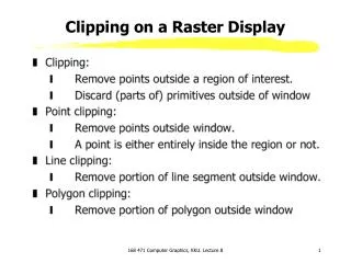
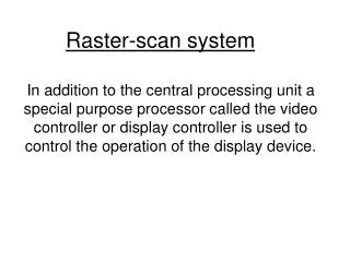
Introduction to Raster scan display. C A E D C Computer Aided Engineering Design Centre. EXAMPLE RASTER GRAPHICS ARCHITECTURE. Raster Scan Displays (1). Raster. Raster: A rectangular array of points or dots.

E N D
Introduction to Raster scan display C A E D C Computer Aided Engineering Design Centre
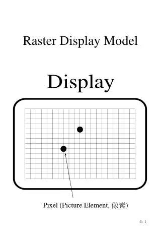
Raster Scan Displays (1) Raster • Raster: A rectangular array of points or dots. • Pixel: One dot or picture element of the raster. Its intensity range for pixels depends on capability of the system.
Scan line: A row of pixels • Picture elements are stored in a memory called frame buffer.
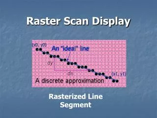
Raster • derived from TV systems for a row of pixels • commonly referred to as a scan line • does influence algorithms – reducing memory requirements, parallelism, etc. • is the derivation of rasterization, scan-line algorithms 1 2 3 4 5 6 7 Raster Scan
Raster Scan Displays (2) • Frame must be “refreshed” to draw new images • As new pixels are struck by electron beam, others are decaying • Electron beam must hit all pixels frequently to eliminate flicker • Critical fusion frequency • Typically 60 times/sec • Varies with intensity, individuals, phospher persistence, lighting...
Raster Scan Displays (3) • Intensity of pixels depends on the system for example black and white screens each point can be on or off thus it needs one bit of memory to represent each pixel. • To paint color screen additional bits are needed. If three bits are used, then number of different colors are 2*2*2. • A special memory is used to store the image with scan-out synchronous to the raster. We call this the frame buffer.
1/30 Sec 1/30 Sec 1/60 Sec 1/60 Sec 1/60 Sec 1/60 Sec Field 1 Field 2 Field 2 Field 1 Frame Frame Raster Scan Displays (4) • Interlaced Scanning • Assume can only scan 30 times / second • To reduce flicker, divide frame into two “fields” of odd and even lines
Raster Scan Displays (5) Scanning (left to right, top to bottom) • Vertical Sync Pulse: Signals the start of the next field • Vertical Retrace: Time needed to get from the bottom of the current field to the top of the next field • Horizontal Sync Pulse: Signals the start of the new scan line • Horizontal Retrace: The time needed to get from the end of the current scan line to the start of the next scan line interlaced, 2 cycles non-interlaced interlaced, cycle 1 interlaced, cycle 2
Raster Scan Displays (6) • Raster CRT pros: • Allows solids, not just wire frames • Leverages low-cost CRT technology (i.e., TVs) • Bright! Display emits light • Cons: • Requires screen-size memory array • Discreet sampling (pixels) • Practical limit on size
Frame Buffers • A frame buffer may be thought of as computer memory organized as a two-dimensional array with each (x,y) addressable location corresponding to one pixel. Frame Buffer
Bit Planes or Bit Depth is the number of bits corresponding to each pixel. • A typical frame buffer resolution might be • 640 x 480 x 8 • 1280 x 1024 x 8 • 1280 x 1024 x 24
True Color Display24 bit planes, 8 bits per color gun. 224 = 16,777,216
Raster Displays • Cathode Ray Tubes (CRTs), most “tube” monitors you see. Very common, but big and bulky: A cathode ray tube (CRT) is a specialized vacuum tube in which images are produced when an electron beam strikes a phosphorescent surface. Most desktop computer displays make use of CRTs. The CRT in a computer display is similar to the "picture tube" in a television receiver. • Liquid Crystal Displays (LCDs) - there are two types: 1) transmissive (Shine light through the image-forming element, e.g. laptops, those snazzy new flat panel monitors) 2) reflective (Bounce light off the image-forming element e.g. wrist watches).
shadow mask electron gun screen Color CRT (Shadow Mask) phosphor dot pattern Different phosphor for each color !!!
Electron Gun • Contains a filament that, when heated, emits a stream of electrons. • Electrons are focused with an electromagnet into a sharp beam and directed to a specific point of the face of the picture tube. • The front surface of the picture tube is coated with small phosphor dots. • When the beam hits a phosphor dot it glows with a brightness proportional to the strength of the beam and how often it is excited by the beam.
CRTs • Strong electrical fields and high voltage • Very good resolution • Heavy, not flat
Difficulties with the CRT • Sometimes the convergence point is behind the screen. • The picture appears to be blurred. • The picture appears to be blurred. • The Beam in focus at the center of the screen. • Dynamic focusing
Liquid Crystal Displays (LCDs) • Liquid crystal displays use small flat chips which change their transparency properties when a voltage is applied. • LCD elements are arranged in an n x m array call the LCD matrix. • Level of voltage controls gray levels. • LCDs elements do not emit light, use backlights behind the LCD matrix
Liquid Crystal Displays (LCDs) • Color is obtained by placing filters in front of each LCD element. • Usually black space between pixels to separate the filters. • Because of the physical nature of the LCD matrix, it is difficult to make the individual LCD pixels very small. • Image quality dependent on viewing angle.
LCDs • LCD resolution is often quoted as number of color elements not number of RGB triads. Example: 320 horizontal by 240 vertical elements = 76,800 elements Equivalent to 76,800/3 = 25,500 RGB pixels "Pixel Resolution" is 185 by 139 (320/1.73, 240/1.73)
LCDs (cont.) • Active LCD screens • Each element contains a small transistor that maintains the voltage until the next refresh cycle. • Higher contrast and much faster response than passive LCD • Passive LCD screens • Cycle through each element of the LCD matrix applying the voltage required for that element. • Once aligned with the electric field the molecules in the LCD will hold their alignment for a short time
Advantages of LCDs • Flat • Lightweight • Low power consumption
LCD vs. CRT • Three times brighter • Five times more contrast. • TFT technology more efficient. • Uses less electricity. • TFT technology more efficient. • Uses less electricity. • Takes less space. • Emits less radiation. • Distortion free viewing. • No flickering. • Narrow viewing angle. • Resolution