Download
1 / 72
720 likes | 875 Views
Propagation models. Okumura Hata COST 231-Hata COST 231-Walfish-Ikegami. OKUMURA MODEL (Toki o ) (1968) Quasi-smooth terrain f = 100-3000 MHz link 1-100 km ref. ant. height , Terrain related parameters Effective base station antenna height Terrain undulation height h

E N D
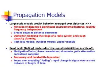
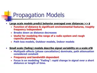
Propagation models • Okumura • Hata • COST 231-Hata • COST 231-Walfish-Ikegami
OKUMURA MODEL (Tokio) (1968) Quasi-smooth terrain f = 100-3000 MHz link 1-100 km ref. ant. height, Terrain related parameters Effective base station antenna height Terrain undulation height h Isolated ridge height Average slope Mixed land-sea parameter
HATA MODEL (1980) Established empirical mathematical forms to Okumura curves Quasi-smooth terrain
Hata Small or medium sized city Large city Suburban area
COST231-Hata[1999] • extension to 1500-2000 MHz band centers, fc300MHz centers, fc<300MHz medium city and suburban Medium sized city and suburban areas metropolitan centers
COST 231 Walfish-Ikegami model Frequency f: 800 - 2000 MHz Base Station Antenna Height hb : 4 - 50 m MS Antenna Height hm : 1 - 3 m Distance d: 0.02 - 5 km BS No line of sight between BS and MS Line of sight between BS and MS (street canyon)
Mikrocellás terjedési modellek • COST231/Walfish-Ikegami modell Pannon GSM előadás 2001. Július 9-11. Slide 9
Trunking in cellular systems Erlang, a Danish mathematician embarked on the study of how a large population could be accomodated by a limited number of servers (Telephone centers) The traffic intensity offered by each user is equal to the call request rate multiplied by the holding time. That is, each user generates a traffic intensity of Au Erlangs given by Au=H
Trunking in cellular systems Au=H where H is the average duration of the call and is the average number of call request per unit time. For a system containing U users and an unspecified number of channels, the total offered traffic intensity A, is given as A=UAu
is the average number of call request per unit time the probability (average number) of ending a call if i servers (lines, channels) are busy Markov chain
Example A cellular system has 394 cells with 19 channels each. Find the number of users that can be supported at 2% blocking if each user averages 2 calls per hour at an average call duration of 3 minutes. Assuming that the system is operated at maximum capacity.
Solution Solution: Probability of blocking = B = 2% = 0.02 Number of channels per cells used in the system, C = 19 Traffic intensity per user, Au = H = 2*(3min/60min) = 0.1 Erlangs For B = 0.02 and C = 19, from the Erlang B chart, the total carried traffic in a cell, A, is obtained as 12.33 Erlangs. Therefore, the number of users that can be supported per cell is U = A/Au = 12.33/0.1 = 123.3 Since there are 394 cells, the total number of subscribers that can be supported by the system is equal to 123.3*394 = 48580.
Brief history • 1982 „Groupe Spécial Mobile” is created within CEPT (Conférence Européenne des Postes et Télécommunications) • 1987 Main Radio transmission techniques are chosen, based on prototype evaluation (1986) • 1989 GSM becomes an ETSI technical committee • 1990 The Phase I GSM900 specification are frozen DCS1800 adaptation starts • 1991 First systems are running DCS 1800 specifications are frozen • 1992 All major European GSM 900 operators begin commercial operations
Consequences of Mobility • Location management (Idle mobile) • location updating – location area • Handover (Call in progress mode) – change the serving cell • Intra cell handover • Inter cell handover • Roaming
Services • Speech service • Full rate coding • Half rate coding • Data service • Up to 9600 bps – phase I • 14.5 Kbps – modified channel coding • HSCSD – High Speed Circuit Switched Data • GPRS – General Packet Radio Service • EDGE – Enhanced Data Rate for GSM evolution
The GSM network can be divided into four main parts: • The Mobile Station (MS). • The Base Station Subsystem (BSS). • The Network and Switching Subsystem (NSS). • The Operation and Support Subsystem (OSS).
GSM PLMN OSS PSTN ISDN MS Base Station Subsystem Network and Switching Subsystem
Mobile Station A Mobile Station consists of two main elements: The mobile equipment or terminal. There are different types of terminals distinguished principally by their power and application: The `fixed' terminals are the ones installed in cars. Their maximum allowed output power is 20 W. The GSM portable terminals can also be installed in vehicles. Their maximum allowed output power is 8W. The handhels terminals have experienced the biggest success thanks to thei weight and volume, which are continuously decreasing. These terminals can emit up to 2 W. The evolution of technologies allows to decrease the maximum allowed power to 0.8 W. The Subscriber Identity Module (SIM).
Mobile Station A Mobile Station consists of two main elements: The mobile equipment or terminal. The Subscriber Identity Module (SIM). • The SIM is a smart card that identifies the terminal. By inserting the SIM card into the terminal, the user can have access to all the subscribed services. Without the SIM card, the terminal is not operational. • The SIM card is protected by a four-digit Personal Identification Number (PIN). In order to identify the subscriber to the system, the SIM card contains some parameters of the user such as its International Mobile Subscriber Identity (IMSI). • Another advantage of the SIM card is the mobility of the users. In fact, the only element that personalizes a terminal is the SIM card. Therefore, the user can have access to its subscribed services in any terminal using its SIM card.
The Base Station Subsystem • The BSS connects the Mobile Station and the NSS. It is in charge of the transmission and reception. The BSS can be divided into two parts: • The Base Transceiver Station (BTS) or Base Station. The BTS corresponds to the transceivers and antennas used in each cell of the network. A BTS is usually placed in the center of a cell. Its transmitting power defines the size of a cell. Each BTS has between one and sixteen transceivers depending on the density of users in the cell. • The Base Station Controller (BSC). The BSC controls a group of BTS and manages their radio ressources. A BSC is principally in charge of handovers, frequency hopping, exchange functions and control of the radio frequency power levels of the BTSs.
The Network and Switching Subsystem The Mobile services Switching Center (MSC) It is the central component of the NSS. The MSC performs the switching functions of the network. It also provides connection to other networks. The Gateway Mobile services Switching Center (GMSC) A gateway is a node interconnecting two networks. The GMSC is the interface between the mobile cellular network and the PSTN. It is in charge of routing calls from the fixed network towards a GSM user. The GMSC is often implemented in the same machines as the MSC.
Home Location Register (HLR) • The HLR is considered as a very important database that stores information of the suscribers belonging to the covering area of a MSC. It also stores the current location of these subscribers and the services to which they have access. The location of the subscriber corresponds to the SS7 address of the Visitor Location Register (VLR) associated to the terminal.
Visitor Location Register (VLR) • The VLR contains information from a subscriber's HLR necessary in order to provide the subscribed services to visiting users. When a subscriber enters the covering area of a new MSC, the VLR associated to this MSC will request information about the new subscriber to its corresponding HLR. The VLR will then have enough information in order to assure the subscribed services without needing to ask the HLR each time a communication is established. • The VLR is always implemented together with a MSC; so the area under control of the MSC is also the area under control of the VLR.
The Authentication Center (AuC) The AuC register is used for security purposes. It provides the parameters needed for authentication and encryption functions. These parameters help to verify the user's identity. The Equipment Identity Register (EIR) The EIR is also used for security purposes. It is a register containing information about the mobile equipments. More particularly, it contains a list of all valid terminals. A terminal is identified by its International Mobile Equipment Identity (IMEI). The EIR allows then to forbid calls from stolen or unauthorized terminals (e.g, a terminal which does not respect the specifications concerning the output RF power).
The Operation and Support Subsystem (OSS) • The OSS is connected to the different components of the NSS and to the BSC, in order to control and monitor the GSM system. It is also in charge of controlling the traffic load of the BSS. • However, the increasing number of base stations, due to the development of cellular radio networks, has provoked that some of the maintenance tasks are transfered to the BTS. This transfer decreases considerably the costs of the maintenance of the system.
MS - Mobile Station MT (Mobile Termination) and TE (Terminal Equipment), Telephony Eq. or DTE (Data Terminal Equipment) BSS - Base Station Subsystem BS Base Station BTS - Base Transceiver Station BSC - Base Station Controller) MSC - Mobile Switching Centre Connection to (PSTN - Public Switched Telephon Network), ISDN, PSPDN, CSPDN HLR - Home Location Register IMSI (International Mobile Subscriber Identity) - (AUC -Authentication Centre)Data of stolen eq., VLR - Visitor Location Register TMSI - Temporary Mobile Subscriber Identity OMC (Operations and Maintenance Centre), NMC (Network Management Centre), ADC (Administration Centre)
The GSM functions • Transmission. • Radio Resources management (RR). • Mobility Management (MM). • Communication Management (CM). • Operation, Administration and Maintenance (OAM).
Radio Resources management (RR) • Channel assignment, change and release. • Handover. • Frequency hopping. • Power-level control. • Discontinuous transmission and reception. • Timing advance.
Handover • Handover of channels in the same cell. • Handover of cells controlled by the same BSC. • Handover of cells belonging to the same MSC but controlled by different BSCs. • Handover of cells controlled by different MSCs.
Handover algorithms • Two basic algorithms are used for the handover: • The `minimum acceptable performance' algorithm. When the quality of the transmission decreases (i.e the signal is deteriorated), the power level of the mobile is increased. This is done until the increase of the power level has no effect on the quality of the signal. When this happens, a handover is performed. • The `power budget' algorithm. This algorithm performs a handover, instead of continuously increasing the power level, in order to obtain a good communication quality.
Mobility Management • The MM function is in charge of all the aspects related with the mobility of the user, specially the location management and the authentication and security.
Location management • When a mobile station is powered on, it performs a location update procedure by indicating its IMSI to the network. The first location update procedure is called the IMSI attach procedure. • The mobile station also performs location updating, in order to indicate its current location, when it moves to a new Location Area or a different PLMN. This location updating message is sent to the new MSC/VLR, which gives the location information to the subscriber's HLR. If the mobile station is authorized in the new MSC/VLR, the subscriber's HLR cancells the registration of the mobile station with the old MSC/VLR. • A location updating is also performed periodically. If after the updating time period, the mobile station has not registered, it is then deregistered. • When a mobile station is powered off, it performs an IMSI detach procedure in order to tell the network that it is no longer connected.
Authentication and security • The authentication procedure involves the SIM card and the Authentication Center. A secret key, stored in the SIM card and the AuC, and a ciphering algorithm called A3 are used in order to verify the authenticity of the user. The mobile station and the AuC compute a SRES using the secret key, the algorithm A3 and a random number generated by the AuC. If the two computed SRES are the same, the subscriber is authenticated. The different services to which the subscriber has access are also checked. • Another security procedure is to check the equipment identity. If the IMEI number of the mobile is authorized in the EIR, the mobile station is allowed to connect the network. • In order to assure user confidentiality, the user is registered with a Temporary Mobile Subscriber Identity (TMSI) after its first location update procedure. • Ciphering is another option to guarantee a very strong security.
Call Control (CC) • The CC is responsible for call establishing, maintaining and releasing as well as for selecting the type of service. One of the most important functions of the CC is the call routing. In order to reach a mobile subscriber, a user diales the Mobile Subscriber ISDN (MSISDN) number which includes: • a country code • a national destination code identifying the subscriber's operator • a code corresponding to the subscriber's HLR • The call is then passsed to the GMSC (if the call is originated from a fixed network) which knows the HLR corresponding to a certain MISDN number. The GMSC asks the HLR for information helping to the call routing. The HLR requests this information from the subscriber's current VLR. This VLR allocates temporarily a Mobile Station Roaming Number (MSRN) for the call. The MSRN number is the information returned by the HLR to the GMSC. Thanks to the MSRN number, the call is routed to subscriber's current MSC/VLR. In the subscriber's current LA, the mobile is paged.
Frequency allocation • Two frequency bands, of 25 MHz each one, have been allocated for the GSM system: The band 890-915 MHz has been allocated for the uplink direction (transmitting from the mobile station to the base station). The band 935-960 MHz has been allocated for the downlink direction (transmitting from the base station to the mobile station).
Multiple access scheme • The multiple access scheme defines how different simultaneous communications, between different mobile stations situated in different cells, share the GSM radio spectrum. A mix of Frequency Division Multiple Access (FDMA) and Time Division Multiple Access (TDMA), combined with frequency hopping, has been adopted as the multiple access scheme for GSM.