Download
1 / 9
100 likes | 282 Views
Zone Control Air System Why?. Provides room by room comfort control. Reduces equipment run time. Eliminates hot/cold rooms. Works with conventional air conditioning units, fan coils and heat pumps. Enables you to heat or cool only the areas you want, when you want.

E N D
Zone Control Air SystemWhy? Provides room by room comfort control. Reduces equipment run time. Eliminates hot/cold rooms. Works with conventional air conditioning units, fan coils and heat pumps. Enables you to heat or cool only the areas you want, when you want. Saves energy and reduces utility bills up to 50%. Up to 7 modulation rooms( zones)+ proportional electrically motorized BY-PASS. Quick and easy installation.
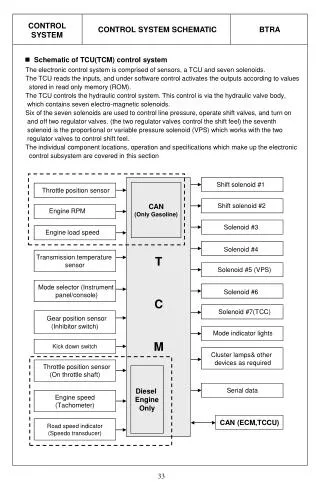
Zone Control Air System What? • ZC207DK is a dry contact controller designed to control up to 7 rooms (zones) with proportional round By-Pass damper • The controller operates the air condition unit (ACU) by two dry contact relays and is not interfering with the Air condition original of the ACU. • The ACUwill receive commands to operate or shut off automatically, according to the total system demand for cooling or heating. • Using our system you can restart the ACU form each room (Zone) . • The controller receives operation commands from each room (zone) and controls the air dampers proportionally. • The advanced Zone control system ZC207DK can beintegrated with any inverter ducted system which will save up to 50% in savingenergy .
Zone Control Air SystemPackageContent • ZC207DK P.C.B Controller • C200PS- Power Supply • 12v Cable • 8 Cables Red/Black (-/+)for the motordamper • P3 Motor ( for the By-Pass Damper ) • Instruction manual
Zone Control Air SystemRoom ( Zone ) Damper Controllers • Operation kit type OPAL RC-11handheld remote controller with I/R receiver. • Operation kit type OPAL 128DDwall mount room thermostat. • Operation kit type OPAL 650DDFlush mount room thermostat. Controllers are Connected to the ZC207DK(12V) with pre fabricated RJ11-4 standard cable supplied by the Manufacturer with the controllers Kits .
Zone Control Air SystemZC207DK • The indication panel will display the status of the system operation • 7 Channel LEDS for each damper status indication. • 2 LED's for each relay operation (Dry Contact). • 1 power LEDS for main power supply. • 1 LED Indication for BY-PASSDamper • 1 LED Indication for fault .
Zone Control Air SystemHow to connect: Easy & Quick installation!
Zone Control Air SystemRelays, EMG and Dip.Switches • Relays • One relay controls the ACU • There are Two relays on the controller that are operating in opposite to each other. • K1 is N.O. and K2 is N.C. (Normally Open and Normally Close). • The installer should select the proper relay as per the type of the Acu. controller if it respectively requires N.O or N.C command . • Use pre-fabricated cables two wires cables between the ZC207DK and the Acu. control board supplied by the ACU. Manufacturer , that match to his terminals at the air condition unit and the other end of the cable to the ZC207DK on the N.O or N.C relay. • EMG = Emergency input • The Emergency input will be N.C. contact input and it requires a jumper wire to operate. • It is mainly designed for fire systems: in Case of FIRE the Air condition will shut down and All Dampers ( also the BY-Pass) will close to avoid toxic gas( Smoke) to go through the ducting into therooms ( zones) • For low voltage input only use 0.5 mm wire as minimum. • Dip. Switches • 8 Dip. Switches will operate different software options. • Dip #1.=Define that at Channel #1 the size of the damper is doubled , or using 2 Dampers of 8” (200mm ) and one control operation . • Dip # 2 = Define if the K1 relay will have 1 second pulse after power up or not . (For Sanyo unit). • Dip # 3 to # 8 = Not to use .
THANK YOU FOR YOUR ATTENTION