Download
1 / 61
610 likes | 719 Views
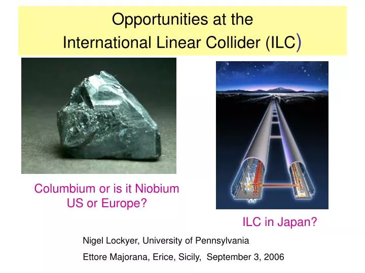
Opportunities at the International Linear Collider (ILC ). Columbium or is it Niobium US or Europe?. ILC in Japan?. Nigel Lockyer, University of Pennsylvania Ettore Majorana, Erice, Sicily, September 3, 2006. Particle Physics Progress 21 th Century. Physicists want a grand View

E N D
Opportunities at the International Linear Collider (ILC) Columbium or is it Niobium US or Europe? ILC in Japan? Nigel Lockyer, University of Pennsylvania Ettore Majorana, Erice, Sicily, September 3, 2006
Particle Physics Progress 21th Century Physicists want a grand View of the landscape Are We Close to the Top? String theorist Burt Ovrut hanging from a rope
The Progress • Standard model of particle physics is a triumph of 20th century physics • Standard Electroweak model describes all measurements to O(0.1%) • MUST add pure EWK radiative corrections sensitive to mass of the top quark in order for results to be consistent • Standard Model is a gauge theory massless particles • Electroweak symmetry breaking gives mass to W, Z, quarks and leptons • The EW precision measurements (LEP/SLC+Tevatron) favor a fundamental scalar at low mass (HIGGS) • Unstable quantum corrections to Higgs mass tells us new physics at energy scales of O(1 TeV) needed to stabilize Higgs mass… . Goal: Explore TeV Energy Range
Precision Electroweak Tests of SM Many of the uncertainties at the level of one part per thousand Z mass 2,000th of 1%! Z-line shape Invisible Width N = 2.9841 0.0083 Number of light neutrino species:
A Successful Pattern of Hadron Colliders Complementing e+e- Colliders • UA1 and UA2 discovered the W and Z bosons at a hadron collider • LEP approved before Z discovered LEP/SLC moved Particle Physics well beyond UA1/UA2 Discovery • LEP searches and precision measurements eliminated many models eg. Leptoquarks • 3 families of neutrinos • Minimal SUSY (MSSM) still consistent with all the data, hence it is still the most possible extension of the standard model Top Discovery at Tevatron (CDF & D0) • We have “great confidence” that a Higgs exists or something that performs that function at the TeV scale “Higgs must exist” Susskind, Erice 2006
Motivating Questions • Are there undiscovered new symmetries or laws in nature? • Are there extra dimensions of space? • Do all the forces become one? • How can we solve the mystery of Dark Energy? • What is Dark Matter? • What happened to the anti-matter?
Evolution of Accelerators 9km/13cm = 69,231 14TeV/80keV = 175,000,000 Technology of accelerators has made huge gains
Discovery of the Century at LHC? ILC will help dig down and uncover deeper picture
International Linear Collider: Performance Specification (White Paper) • Initial maximum energy of 500 GeV, operable over the range 200-500 GeV for physics running. • Equivalent (scaled by 500 GeV/s) integrated luminosity for the first four years after commissioning of 500 fb-1. • Ability to perform energy scans with minimal changeover times. • Beam energy stability and precision of 0.1%. • Capability of 80% electron beam polarization over the range 200-500 GeV. • Two interaction regions, at least one of which allows for a crossing angleenabling gg collisions. • Ability to operate at 90 GeV for calibration running. • Machine upgradeable to approximately 1 TeV.
Key Points for Why We Want the ILC • Precision Higgs Factory • Measurements are a window to new physics • New physics is expected at the TeV scale Synergy with LHC Discoveries • Discoveries lead to questions such as: • Standard model Higgs? Measure couplings, spin, parity • Is that supersymmetry? Measure spin and quantum nos. • Is that neutralino “dark matter” Measure mass to 1% • How many extra dimensions are there? LHC+ILC best
etc.. etc.. Higgs at ILC Higgs Self Coupling • Little Higgs Model • Quadratic divergence of the Higgs • boson mass can be cancelled by extra • fermions and bosons about 1TeV. • Higgs-less Model • A new model based on 5 dim space-time. The unitarity of the WW scattering is saved • by the Kaluza-Klein modes of the gauge bosons. • Crucial information on Higgs potential • Self coupling to 10%(Yamashita) 4 b-jets 80% efficiency 2 years running
ILC has Powerful Recoil Technique In e+ e- Z + anything (even invisible decay products) the recoil mass of system is determined by kinematics and conservation of energy. Peak in recoil mass corresponds to Higgs Sensitive to invisible Higgs decay
Measuring the Higgs Spin and Parity Miller et al. Scan hZ production near threshold Can unambiguously show that JP=0+ 20 fb-1 per point Difficult to do at LHC
l+ e+ Z l- Z* H e- Powerful Test at ILC At ILC : (6% of Z decays) The absolute cross section of e+ e- Z* Zh involves vertex that gives Z its mass. Sum rule tests whether observed h0 generates all mass of the Z boson. LHC measures ratios of couplings and cannot determine the ZZh coupling directly. If the production rate is smaller, then multiple h0 bosons must be contributing to Z mass.
Higgs Branching Ratios Measure Higgs decay branching ratios by measuring system that recoils against Z This level of precision only possible at ILC qualitatively different from LHC (Hinchliffe)
Perform accurate & Model Independentmeasurements of the Higgs Couplings Look for deviation from straight line SUSY and Extra Dimension Models can behave differently The strength of the Higgs couplings to fermions and bosons is given by the mass of the particle Critical Test f ~ mf Higgs - f Small uncertainties Important to detect cleanly all quarks From Joanne Hewitt
Precision SUSY at ILC • ILC has a central role to play in SUSY • SUSY observables at ILC qualitatively beyond LHC (Peskin) • Super particles could be heavy but lightest chargino should be seen at 500 GeV ILC (proposed initial energy). • All charginos and neutralinos should be seen at a 1 TeV ILC • Definitive determination of spin and quantum numbers • Mass of lightest super symmetric particle to 1% (LHC 10%) • Precision mass measurements of super particles • Measure chargino and neutralino mixing (higgsino and gaugino) • If neutralino is lightest super particle and R-parity conserved then it is stable and a dark matter candidate • Only ILC provides accurate enough input for dark matter relic abundance calculations which seem to get in ball park of WMAP allowed range
New Gauge Bosons Riemann Indirect sensitivity beyond LHC even at 500 GeV Measure Z΄ couplings given mass from LHC
ITRP (Wise Cold People)(International Technology Recommendation Panel) “This recommendation is made with the understanding that we are recommending a technology, not a design.” August 20th, 2004 Super conducting RF is accelerating technology choice (Global all aboard!)
ILC Design Needed Good Start
GDE RDR / R&D Organization FALC ICFA FALC Resource Board ILCSC GDE Directorate GDE GDE Executive Committee GDE R & D Board GDE Change Control Board GDE Design Cost Board Global R&D Program RDR Design Matrix
Baseline Reference Design Report 2006 July Dec Jan Frascati Bangalore Vancouver Valencia Freeze Configuration Organize for RDR Review Design/Cost Methodology Review Initial Design / Cost Review Final Design / Cost RDR Document Design and Costing Preliminary RDR Released
~31 km 20mr ML ~10km (G = 31.5MV/m) RTML ~1.6km BDS 5km 2mr e+ undulator @ 150 GeV (~1.2km) R = 955m E = 5 GeV x2 not to scale The ILC Baseline Machine
Positron-style room-temperature accelerating section E=70-100 MeV laser standard ILC SCRF modules diagnostics section sub-harmonic bunchers + solenoids Baseline Electron Source • DC Guns incorporating photocathode illuminated by a Ti: Sapphire drive laser. • Long electron microbunches (~2 ns) are bunched in a bunching section • Accelerated in a room temperature linac to about 100 MeV and SRF linac to 5 GeV.
Primary e- source Beam Delivery System IP 250 GeV e- DR Positron Linac 150 GeV 100 GeV Helical Undulator In By-Pass Line Photon Collimators e+ DR Target e- Dump Photon Beam Dump Photon Target Adiabatic Matching Device e+ pre-accelerator ~5GeV Auxiliary e- Source Baseline Positron Source • Helical Undulator Based Positron Source with Keep Alive System • The undulator source will be placed at the 150 GeV point in main electron linac. • This will allow constant charge operation across the foreseen centre-of-mass energy operating range.
Baseline ILC Cryomodule • The baseline ILC Cryomodule will have 8 9-Cell cavities per cryomodule. The quadrupole will be at the center in the baseline design. • Every 4th cryomodule in the linac would include a quadrupole with a corrector and BPM package.
ILC Damping Ring: Baseline Design • Positrons: Two rings of ~ 6 km circumference in a single tunnel. • Two rings are needed to reduce e-cloud effects unless significant progress can be made with mitigation techniques. • Preferred to 17 km due to: • Space-charge effects • Acceptance • Tunnel layout (commissioning time, stray fields) • Electrons: one 6 km ring. • Preferred to 3 km due to: • Larger gaps between mini-trains for clearing ions. • Injection and extraction kickers ‘low risk’
RF Power: Baseline Klystrons Specification: 10MW MBK 1.5ms pulse 65% efficiency Thales CPI Toshiba ILC (XFEL @ DESY) has a very limited experience with these Klystrons. Production and operation of these Klystron are issues that needs to be addressed.
Beam Delivery System (BDS) • Baseline (supported, at the moment, by GDE exec) • two BDSs, 20/2mrad, 2 detectors, 2 longitudinally separated IR halls • Alternative 1 • two BDSs, 20/2mrad, 2 detectors in single IR hall @ Z=0 • Alternative 2 • single IR/BDS, collider hall long enough for two push-pull detectors
Sub-Systems 43MW Main Linacs 97MW RF: 76MW Injectors Cryogenics: 21MW Damping rings 78% BDS Auxiliaries 65% 60% Beam 22.6MW Site power: 140 MW (500 GeVbaseline)
ILC is a Truly Global Project • Project initiated by three regions of world • Design performed in all three regions of world • R&D is all three regions • Test Facilities in all three regions • Accelerator Physicists Work Well Together • Decision on site will be global, as was technology decision • US will bid to Host (DOE working towards this goal)
Main ILC R&D Issue Produce high gradient cavities reliably
SRF Cavity Gradient * assuming 75% fill factor Total length of one 500 GeV linac 20km
Cavities for Module 6 @ DESY 35 35 36 32 34
ILC Main Linac Accelerator R&D Goals • The ILC-Global Design Effort (GDE)’s priorities as being discussed by the S0, S1 and S2 Task Forces. Still being defined…present stage the goals being discussed are: • Develop cavity processing parameters for a reproducible cavity gradient of 35 MV/m; improve the yield of 9-cell cavities for gradient of 35 MV/m in vertical tests (S0). Carry out parallel/coupled R&D on cavity processing, fabrication and materials to identify paths to success. • Assemble and test one or more cryomodules with average gradient > 31.5 MV/m (S1). • Build and test one or more ILC rf units at ILC beam parameters, high gradient, and full pulse rep rate (S2.1) • To develop plans for an ILC Main Linac System Test consisting of several rf units (S2.2). To achieve the goals, R&D plan will also strengthen the technical capabilities and infrastructure of collaborating institutions.
Global Plan Emerging Back to Basics
Re-entrant CornellKEK Low Loss Jlab KEK Tesla Shape New Shapes Breakthrough 50 MV/m in Single Cells !Lower Surface Magnetic Field & Lower Losses Need Multi-cells Next
Higher Gradient in Single Cell: Eacc = 47 - 52 MV/m Fabricated at Cornell Ichiro @ KEK
ILC Cavity Material Grain size R&D Ningxia • The single cell and/or large grain Niobium shows considerable promise in achieving higher gradient. • R&D activities are under way at KEK, Jlab and DESY using single cell cavities. • It could eliminate the need to electro-polish • Two 9-cell cavities are being fabricated. Heraeus
ACCEL AES US: ILC Cavity R&D • In order to make timely progress on the ILC cavities gradient goal Fermilab has taken the approach that • Maximizes the utilization of existing U.S. SRF infrastructure • While developing Fermilab based expertise and infrastructure. 60 Cavities (by FY07)
R&D Around the World Three Regions-only look at DESY, KEK, US
KEK: Main Linac SRF Unit R&D Goal: Achieve Higher Gradient >40 MV/m in a new Cavity Design Parallel Fermilab but emphasis on high gradient
The assembly of a string of 8 cavities into a string. Class 100 clean room Facilities being setup at Fermilab as part of SMTF. The inter-cavity connection is done in class 10 cleanroom DESY String Assembly
INFN/DESY Co-Axial Tuner Lorentz Force Detuning Micro-phonics Successfully operated with superstructures Piezo-tuner integration still pending
The module assembly is well defined and about 10 modules have been made of several designs ILC will need about 4000 modules. DESY Module Assembly