Download
1 / 15
150 likes | 221 Views
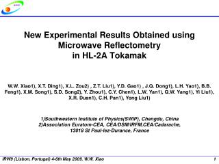
J. Q. Dong* for HL-2A Team Southwestern Institute of Physics, Chengdu, China. Brief Introduction of Recent Physics Experiments on HL-2A Tokamak. In collaboration with University of Science and Technology of China, Hefei, China University of California at San Diego, USA

E N D
J. Q. Dong* for HL-2A Team Southwestern Institute of Physics, Chengdu, China Brief Introduction of Recent Physics Experiments on HL-2A Tokamak In collaboration with University of Science and Technology of China, Hefei, China University of California at San Diego, USA CEA, IRFM, Cadarache, France WCICenter for Fusion Theory, Daejeon, Korea NIFS, Toki, Japan Kyoto University, Kyoto, Japan Kyushu University, Kasuga, Japan ASIPP, Hefei, China * Also at IFTS, Zhejiang University, China 6th US-PRC Magnetic Fusion Workshop 10-12 July, 2012, UCSD, San Diego, USA
Outline • 1. Introduction • 2. Experimental results • ELM mitigation • Turbulence and flows in L-I-L(H) transitions • Blob generation • Coexistence of multi-Alfven-modes • Frequency jump and chirping of fishbone modes • Neoclassical tearing modes • 3. Summary
1. Introduction ECRH system toroidal cross-section poloidal cross-section 1# 6# 2# 4# 3# 3# 5# 6 gyrotrons installed
SMBI/LFS: using electro-magnetically driven valve with a cylindrical hole of diameter~0.2 mm to generate a supersonic molecular beam SMB characteristics: measured by three Da arrays and a CCD camera Valve temperature:room temperature; liquid nitrogen temperature Two gas tanks: H2/D2; He/Ne/Ar Gas pressure: 0.2 – 4.0 MPa Pulse duration: 0.3 ~ 50 ms @ 1~50Hz L.H. Yao, Nucl. Fusion 47 (2007)1399 SMBI/HFS: using a pneumatic injector, in which accelerated pistons are used to compress the working gas and then open the Laval nozzle. Gas pressure: 0.2–1.0MPa Pulse duration:~5 ms @5-10 Hz Experimental setup of the SMBI system with both LFS and HFS injection on HL-2A Supersonic Molecular Beam (Cluster Jet) Injection system • SMBI was first successfully developed and used on the HL-1M tokamak and then used on many other fusion devices. • The fuelling efficiency of LFS-SMBI into ohmic plasma is estimated as 40~60% for a limiter configuration and 30-40 % for a divertor configuration
3D Langmuir probe arrays • Sampling rate = 1 MHz • Spatial resolution= 4mm • Diameter of tips is 1.5 mm. • Height of tips is 3 mm. PP TSLP • Parameters measured simultaneously: etc. at a few radial and poloidal positions in two poloidal sections
2. Experimental results ELM mitigation (1) (a) (b) ELM mitigation with SMBI and CJI (c) ELM mitigation with (a)SMBI, (b)CJI, and (c)He SMBI. ~ 2-3.5 is achieved and the amplitude is reduced by the same amount.
ELM mitigation (2) It seems that the density gradient in the pedestal region is reduced by the SMBI.
Turbulences and flows in L-I-L (H) transitions • L-mode: Pe’ oscillation is • less than 5%, density • fluctuations are large and not • correlated with Pe’ oscillation. • I-phase: turbulence is • correlated and out of phase • with Pe’ oscillation . • H-mode: density gradient increases, • fluctuations of 55-60 kHz and m/n=(15-18)/(4-5) exist between ELMs, • Er and Is are in phase. Also see G. Tynan et al. on Wednesday
Blob generation Two-dimensional images of conditional average of the floating potentials across the LCFS at six times of 2 s interval. Contour plot of the cross conditional average between turbulence energy and electron density fluctuations as a function of frequency and delay time,
Coexistence of multi-Alfven-modes (1) • The coexistence of multi-Alfven-modes induced by energetic electrons were observed in high power ECRH plasmas with the plasma parameters: • Ip=155kA-160 kA, • Bt = 1.2T-1.4 T • <ne> < 1.4×1013cm-3. • PECRH > 0.6 MW
Coexistence of multi-Alfven modes (2) • The evolution of the soft x-ray spectra with different channels • The signals of the edge channels of the soft x-ray array show the similar frequency spectra with that of Mirnov coils. • The signals are very weak or even disappear in the center channels. • The modes are located in the outer region the plasma.
Frequency jump and chirping of fishbone modes • The frequency jump is observed for ECRH power higher than 810 kW; • Frequency chirping down is observed for ECRH power higher than 700 kW.
3/2 NTM during ELMy H-mode m/n=3/2 mode survives m/n=2/1 mode disappears late Ip=300kA,Bt=2.4T, ne~3×10¹⁹m-3 PECRH~1.5MW, PNBI~0.8MW βN (onset) ~0.7
3. Summary • Heating, fueling and diagnostics systems have been upgraded. • Topics of H-mode physics, such as ELM mitigation , L-I-H transition and pedestal dynamics are under intensive investigation. • The spatial structure of zonal flow, GAM and blob, the shear flow-turbulence dynamics are investigated . • Multi-Alfve´n modes excited by energetic electrons are observed with high power ECRH. • Frequency jump and chirping of fishbone modes excited by energetic electrons are investigated. • NTMs are observed in H-mode discharges. • Collaborations with US institutions were started and more are welcome.
Thank you for your attention!