Download
1 / 35
350 likes | 433 Views
P11213: Modular Student Attachment to the Land Vehicle for Education. Jared Wolff, Andrew Komendat, Oyetunde Jolaoye , Dylan Rider. Contents. Project Goals Customer Needs Engineering Specifications Concept Selection Design Considerations Student Project Prototype Testing

E N D
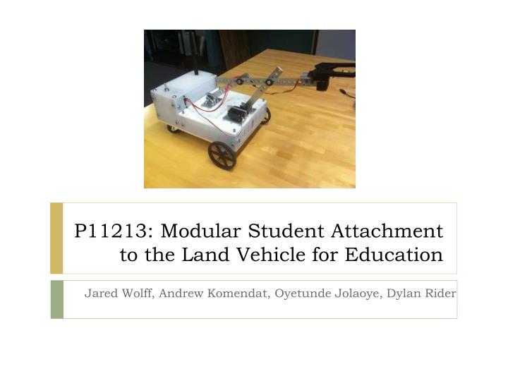
P11213: Modular Student Attachment to the Land Vehicle for Education Jared Wolff, Andrew Komendat, OyetundeJolaoye, Dylan Rider
Contents • Project Goals • Customer Needs • Engineering Specifications • Concept Selection • Design Considerations • Student Project • Prototype • Testing • Results and Status • Future Plans and Suggestions
Project Goals • Attachment to Land Vehicle for Education (LVE) • Introduce freshman engineers to design tools and processes • Removable and interchangeable Modular Student Attachment (MSA) • Utilize RIT facilities • Hands on example • Team project
Customer Needs Some significant customer needs: • The MSA must teach first year RIT Mechanical Engineering students design principles. • MSA must also utilize in house facilities for the manufacturing of MSA components. • MSA must be of a low cost so that more would be purchased, • MSA must be easy to store in the allocated storage and it must also be safe to use. • MSA must be impressive such that other schools and faculty would want to emulate it.
Engineering Specifications Some engineering specifications: • MSA shall require each student to design, model, and manufacture 1 to 3 parts • MSA shall required assembly in CAD of 5 to 15 parts • MSA shall include at least 5 components • MSA shall have less than 10 customable parts • MSA shall require between 0.5 and 2 hours to teach per class • MSA shall have not exceed 5 pounds, including payload • MSA shall require less than 5 repairs during its lifetime
Design Considerations • Feasibility and user friendliness • Detailed motor and torque analysis • Budget limitations • LVE integration and attachment • Control interfacing and communication • Power consumption analysis
Mechanical Design • Front/Aft Motor Interchangeable • Controls integral to LVE • Two motors required
Torque Analysis • Calculator in Matlab • Finds geometric angles based on 90 degree rotation • Uses 9x9 matrix to solve for torque required • Checking tool for professors to validate student design • Help visualize real world limitations
Torque Analysis • Standard square geometry • Full range of motion • No inflection point • No added range in the reach
Torque Analysis • Offset geometry • Full range of motion • Visible inflection point
Torque Analysis • Offset geometry • Full range of motion • Visible inflection point
Power Consumption • 72.2 oz in at 4.8V • 90.3 oz in at 6V • Worse Case Transients ~0.700 mA • Normal Under Load Current ~0.500 mA • 5V provided by the Buck Circuitry • Power = 2*0.500 * 5V = 5W • Current = 1 A
Control Communication • USART Interface • 115200 BAUD • 1 stop bit • Normal Inverted Operation • No parity • Data protocol • All data is sent via UART from the LVE controller.
Structural Analysis • Subject to drop requirements • Limited payload weight • Finite Element Analysis (FEA)
LVE Mounting • Quick attachment and removal • Easy to use • Robust to repeated use • Press fit with cotter pin
Component Selection • Standardized bolt and nut sizes • Off the self gripper, motors • Less customized parts when possible • Budget restrictions
Student Goal • Lift an object from 6-9 inches off the ground between shelves across the room
Student Components and Analysis • Geometric analysis • Computer Aided Drafting (CAD) modeling of designed parts • CAD assemblies using parts library available • Manufacturing • Assembly and test
Student Components and Analysis • Links • Brackets • Pins Student Made Student Made Student Made
Testing • Test plan includes 18 tests • Passed all tests
Testing • 10/3 time to complete ratio • Scrap material
Results and Conclusions • Working prototype • Lacks robustness in strength and durability • Budget restrictions were overlooked • Fun project • Room for improvement • Contains potential multidisciplinary projects
Future Suggestions and Improvements • Better material selection color for aesthetics • Manufacture gripper in house (cost reduction) • More robust and capable drive servo • Decrease size and capability of MSA • Improve multidisciplinary projects
Acknowledgements • Special Thanks To: • Guides: • Phil Bryan • Leo Farnand • Vince Burolla • Sponsors and Faculty Advisors • Dr. Edward Hensel • Dr. Beth Debartolo


![Application Process of Student Visa [F1 & M1 Visa]](https://cdn4.slideserve.com/7160954/slide1-dt.jpg)