Download
1 / 76
760 likes | 959 Views
The Global Positioning System (GPS). Michael Lombardi Chair, SIM Time and Frequency Metrology Working Group National Institute of Standards and Technology (NIST) lombardi@nist.gov. Why do satellite signals work better than ground signals for time transfer ?.

E N D
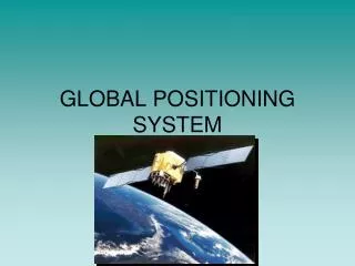
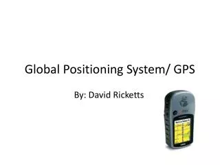
The Global Positioning System (GPS) Michael Lombardi Chair, SIM Time and Frequency Metrology Working Group National Institute of Standards and Technology (NIST) lombardi@nist.gov
Why do satellite signals work better than ground signals for time transfer? • The accuracy of any time transfer system can be no better than the uncertainty of the path delay measurement. Satellite systems have path delays that are easier to measure and calibrate than ground based systems. • The variation in path delay is small due to a clear, unobstructed path between the receiver and transmitter. • The coverage area is usually much larger. • Interference due to weather and ground based noise is usually less of a problem.
Ground-based signals skywave groundwave line-of-sight
LF Radio • Before satellites, the most accurate time signals were sent by LF (low frequency) radio. LF is the part of the spectrum from 30 to 300 kHz, also known as longwave. • LF signals are still used to send time signals to radio controlled clocks on frequencies such as 40, 60, and 77.5 kHz using simple modulation schemes. NIST Radio Station WWVB (60 kHz) is one example.
Disadvantages of LF • Limited coverage area. • Subject to diurnal phase shifts at sunrise and sunset. Over long paths, skywave can interfere with groundwave. • When receiver is unlocked, cycle slips equal to the period of the carrier (16.67 microseconds in the case of 60 kHz) are introduced in the data. • User must calibrate path delay for time transfer, and even then is limited by the cycle ambiguity.
Satellite Signals • The best signals for time transfer. Since the signals originate high above the Earth, there is an clear path between the transmitter and receiver. • Coverage area is worldwide with global navigation systems like GPS. • Small path delay changes occur as the signal passes through these ionosphere and troposphere, but these are measured in nanoseconds.
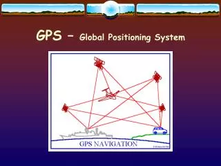
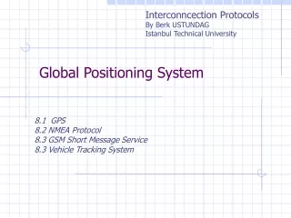
What is GPS? • The Global Positioning System (GPS) is not only a positioning and navigation system, but the main system used to distribute accurate time and frequency worldwide • The constellation includes a maximum of 32 satellites (32 satellites are in orbit as of October 2012) • The satellites are in semi-synchronous orbit at an altitude of about 20,200 km • The orbital period is 11 hours, 58 minutes • At least four (typically seven or more) satellites can always be received at a given location, so the entire Earth has continuous GPS coverage • The satellites carry either cesium or rubidium atomic clocks
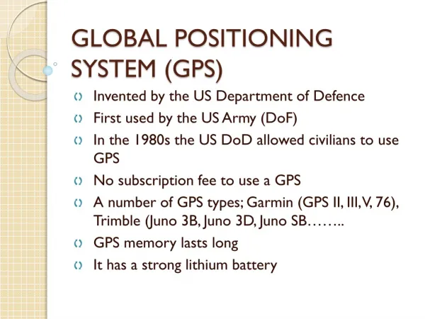
GPS History • Developed by the US Department of Defense • The first prototype GPS satellite was launched in 1978 • Full Operational Capability for GPS was declared in late 1993, prior to that it was considered an experimental system. Many products became available when it was declared operational. • The accuracy of GPS improved significantly in May 2000. This was when the U. S. government removed the intentional errors that were being added to the signals sent to civil users, called Selective Availability (SA). This led to a large demand for GPS products, and the price of GPS equipment dropped dramatically.
Why can GPS be trusted as a reference for measuring position, distance, and time? • GPS requires highly accurate timing derived from atomic clocks, or the navigation system will fail • Assume that the maximum acceptable uncertainty contribution from the GPS clocks is 1 m: • Light travels 3 x 10⁸ m/s, thus a 1 m error equals a 3.3 ns timing uncertainty • The clocks must be stable enough to keep time to better than 3.3 ns for 12 hours, the approximate period between clock corrections • This requires better than 1 x 10-13 stability (3.3 x 10⁻⁹ s / 43200 s = 0.8 x 10⁻¹³) • The atomic oscillators onboard the satellites are steered to agree with the Coordinated Universal Time (UTC) time scale maintained by the U. S. Naval Observatory, known as UTC(USNO). • The time difference between UTC(USNO) and UTC(NIST) is small, usually less than 10 nanoseconds • The GPS signals contain the best estimate of Coordinated Universal Time being broadcast anywhere, and they are available free of charge to anyone, worldwide
Currently (October 2012) there are 32 GPS satellites in orbit occupying all 32 possible “slots” 5 are referenced to cesium clocks 27 are referenced to rubidium clocks The oldest satellite is PRN 32, launched in November 1990, this was a Block IIA satellite built by Rockwell The newest satellite is PRN 24, launched on October 4, 2012, a Block IIF-3 satellite built by Boeing Block II/IIA Vehicles GPS Satellites Block IIR/IIR-M Built by Lockheed Martin Launched 1997 - 2009
GPS Control Segment • The GPS control segment includes a master control station in Colorado, an alternate master control station in California, 12 command and control sites, and 16 monitoring sites that • Monitor the GPS satellites for operational health • Upload satellite almanacs, ephemeris messages, and clock corrections
GPS Signal Structure Two L-band carrier frequencies L1 = 1575.42 MHz L2 = 1227.60 MHz • Two PRN Codes • P(Y): Military Code • 267 day repeat interval • Encrypted – code sequence not published • Available on L1 and L2 • C/A: Coarse Acquisition (Civilian) Code • 1 millisecond repeat interval • Available to all users, but only on L1 • Code modulated with Navigation Message Data • Provides ephemeris data and clock corrections for the GPS satellites • Low data rate (50 bps)
GPS Modulation • The carriers are pure sinusoids. Two binary codes are modulated onto them: the C/A (coarse/acquisition) code and the P (precise) code. • Binary biphase modulation (also known as binary phase shift keying [BPSK]) is the technique used to modulate the codes onto the carrier. There is a 180 degree carrier phase shift each time the code state changes. • The modulation requires a much wider frequency band than the minimum bandwidth required to transmit the information being sent. This is known as spread spectrum modulation. It allows very low signal levels to be used.
Spread Spectrum Communication • “Spreads" the power spectrum of the transmitted data over a wide frequency band at VERY LOW POWER • Same principle is used for household cordless telephones • Each satellite is assigned a unique Pseudo-Random Noise (PRN) Code. All GPS satellites transmit at the same frequency but are identified by their PRN codes.
Relativistic Effects in GPS • GPS is a real world application that makes use of Einstein’s theory of relativity. The oscillators onboard the GPS satellites are given a fixed frequency offset of -4.4645 x 10⁻¹⁰ to compensate for relativistic effects in the GPS satellite orbits. • Second-order Doppler shift – a clock moving in an inertial frame runs slower than a clock at rest. • Gravitational frequency shift – a clock at rest in a lower gravitational potential runs slower than a clock at rest in a higher gravitational potential. • Without this frequency offset, GPS satellite clocks would gain about 38 microseconds per day relative to clocks on the ground. • GPS receivers apply an additional correction of up to 23 ns (6 meters) to account for any eccentricity in the satellites orbit.
GPS Signal (L1 band, C/A Code) P[dBW] 2.046 MHz C/A-CODE -160 P-CODE -163 f [Hz] L1 Signal 1575.42 MHz P[dBW] 20.46 MHz Frequency Spectrum • C/A stands for Coarse Acquisition. This code, broadcast at 1575.42 MHz, is the reference for nearly all GPS consumer products. • It is available on the L1 carrier to anyone, worldwide, as part of the Standard Positioning Service (SPS) of GPS
GPS Positioning • GPS positioning is fundamentally based on: • The precise measurement of time • The constancy of the speed of light • GPS positioning uses the concept of trilateration • GPS satellite positions are known • Receiver position is not known • GPS-to-receiver range measurements are used to compute position
Positioning Example with One Transmitter Receiver(location unknown) Locus of points on which the receiver can be located Measured Range Transmitter(location known)
Positioning Example with Two Transmitters True Receiver Location r2 r1 T1 T2 False Receiver Location
Positioning Example with Three Transmitters True Receiver Location r3 T3 r2 r1 T1 T2
GPS Positioning - II • The position solution involves solving for four unknowns: • Receiver position (x, y, z) • Receiver clock correction • Position accuracy of ~10 m implies knowledge of the receiver clock to within ~30 ns – the speed of light is near 3 ns per meter • Requires simultaneous measurements from four GPS satellites • The receiver makes a range measurement to the GPS satellite by measuring the signal propagation delay • The data message modulated on the GPS signals provides the precise location of the GPS satellite and corrections for the GPS satellite clock errors
Pseudo-Random Noise (PRN) Codes • Each GPS satellite transmits its own unique Pseudo-Random Noise (PRN) Code • The C/A Code repeats every millisecond • The receiver generates replicas of the C/A code and uses code correlation to distinguish between different satellites
Pseudorange Measurements GPS transmitted C(A)-code Receiver replicated C(A)-code Finding Dt for each GPS signal tracked is called “code correlation” Dt • Dt is proportional to the GPS-to-receiver range • Four pseudorange measurements from different satellites are needed to solve for receiver position and time
Ranging ( xs, ys, zs, ts ) --- [m] Satellite PRN sequence Receiver PRN sequence ( x, y, z, t ) pr Receiver pseudo-range --- [s]
Although the primary purpose of GPS is to serve as a positioning and navigation system, the entire system relies on time measurements made with atomic clocks. After the receiver position (x, y, z) is solved for, the solution is stored. Then, given the travel time of the signals (observed) and the exact time when the signal left the satellite (given), time from the clock on the satellite can be transferred to the receiver clock. The measurement made by the GPS receiver reveals the difference between the satellite clock and the receiver clock by measuring the transit time of the signal: time of signal reception, (based on receiver clock,can be significantly in error) time of transmission,encoded in signal byGPS satellite clock (known precisely)
This measurement, when multiplied by the speed of light, produces not the true geometric range but rather the pseudorange, with deviations introduced by the lack of time synchronization between the satellite clock and the receiver clock, by delays introduced by the ionosphere and troposphere, and by multipath and receiver noise. The equation for the pseudorange is • p = ρ + c × (dt− dT) + dion+ dtrop+ rn • where • p is the pseudorange • c is the speed of light • ρ is the geometric range to the satellite • dtand dTare the time offsets of the satellite and receiver clocks with respect to GPS time • dionis the delay through the ionosphere (an estimate can be obtained from the GPS broadcast) • dtropis the delay through the troposphere • rnrepresents the effects of receiver and antenna noise, including multipath.
Finding Position & Time • Two main factors determine the accuracy of the position and time solution • UERE (User Equivalent Range Error) • DOP (Dilution of Precision)
The accuracy of the pseudo-range measurements between a particular satellite and a particular user UERE is the result of several factors: the quality of the broadcast signal in space, which varies from satellite to satellite and time to time the stability of particular satellite’s clock the predictability of the satellite’s orbit User Equivalent Range Error (UERE)
UERE accuracy exceeds published standard N/A N/A N/A N/A N/A 7 Signal-in-Space User Range Error is the difference between a GPS satellite’s navigation data (position and clock) and the truth, projected on the line-of-sight to the user 2001 SPS Performance Standard (RMS over all SPS SIS URE) 6 5 2008 SPS Performance Standard (Worst of any SPS SIS URE) 4 RMS SIS URE (m) RMS Signal-in-Space User Range Error (URE), meters 3 Decreasing range error 2 1.6 1.2 1.1 1.0 0.9 1 0 1990 1992 1994 1996 1997 2001 2004 2006 2008 2009 Selective Availability (SA)
Dilution of Precision (DOP) • depends on the geometry of satellites, as seen by the receiver • used in cooperation with the UERE to forecast navigation and time errors Good (Low) DOP Conditions: Poor (High) DOP Conditions:
GPS Positioning Accuracy Specifications U.S. commitments to civil GPS performance are documented in the GPS Standard Positioning Service Performance Standard (2008).
What is GPS Time? • GPS time is controlled by the United States Naval Observatory (USNO), but not exactly the same thing as UTC(USNO). • GPS time differs from UTC(USNO) by the number of leap seconds that have occurred since the origination of the GPS time scale (January 6, 1980); this value is equal to 16 s as of September 2012, and increases each time there is a leap second. The navigation message contains a leap second correction, however, and GPS receivers automatically correct the time-of-day solution. • GPS time also differs from UTC(USNO) by a small number of nanoseconds that continuously changes. The current difference between UTC(USNO) and GPS time is also in the navigation message, and applied by GPS receivers. • After the leap second and UTC(USNO) corrections are applied, GPS time is nearly always within 15 nanoseconds of UTC(USNO) and UTC(NIST). This is better than the specified accuracy of 40 ns. • When the corrections are applied, GPS provides the best estimate of Coordinate Universal Time available to the general public, and it is available free of change to anyone, worldwide.
Disciplined Oscillators • Disciplined oscillators (DOs) have been used as time and frequency standards for more than 50 years. They use reference signals received by radio to “discipline” (steer) a local oscillator so that its frequency agrees with the incoming reference. • Short-term stability (at intervals shorter than the steering interval is about the same as the LO. • Long-term stability (at intervals of weeks or months) is about the same as the reference. • Medium-term stability (longer than correction interval, but shorter than weeks or months) depends upon the design.
GPS Disciplined Oscillators (GPSDO) • Operated as standalone time and frequency standards • GPSDOs discipline a local oscillator (quartz or rubidium) to agree with the GPS signals. • GPSDOs are self-calibrating standards that will perform at a high level if the device and the GPS constellation are functioning normally. • Produce on-time pulses (1 pps). • Produce standard frequency outputs (such as 1, 5, and 10 MHz).
GPS Antennas • Small and inexpensive, higher gain units (> 35 dB typical) generally used for timing to drive long cables. • These antennas are normally active, with internal amplifiers powered by 5 V dc from the antenna cable. • Most bring the 1575 MHz L1 carrier straight to the receiver, without any down conversion. • Omnidirectional, need to have clear sky view on all sides for best results.
How a GPSDO Works • Most models control the local oscillator with one or more servo loops. One type of servo loop is a phase locked loop (PLL). • A PLL compares the phase of the received GPS signal to the phase of a voltage controlled oscillator (VCO). • The phase detector outputs the phase difference between the two input signals to a loop filter, which in turn sends a control voltage to the VCO. • The control voltage changes the frequency of the VCO in a direction that reduces the phase difference between the VCO and the reference input. The PLL is locked when the phase of the VCO has a constant offset relative to the phase of the reference.
GPSDO (steered local oscillator, no synthesizer) • A phase detector measures the difference between the 1 pps signal from GPS and the signal from the local VCO. • A microcontroller reads the output of the phase detector and monitors the phase difference. When the phase difference changes, the software changes the control voltage sent to the VCO, so that the phase difference is held within a given range.
GPSDO (unsteered local oscillator, synthesizer) • The local oscillator is used as the time base for a frequency synthesizer. The phase of the synthesizer is compared to GPS. A correction is sent to the synthesizer to compensate for the frequency offset and eliminate the phase difference, but no corrections are applied to the LO • Modern direct digital synthesizers (DDS) can allow very small frequency corrections to be made (1 μHz resolution at 10 MHz allows frequency corrections of 1 × 10-13). Allowing the local oscillator to free run often results in better performance than the VCO method, where unexpected shifts in the control voltage can produce unwanted adjustments in the output frequency.